Method for cutting extruded profile sections into lengths

a technology of extruded profile and length, which is applied in the field of cutting an extruded profile section into lengths, can solve the problems of inability to rule, prolong the total production time, and inaccuracy of contours

Inactive Publication Date: 2005-03-08
WKW ERBSLOEH AUTOMOTIVE GMBH
View PDF15 Cites 3 Cited by
  • Summary
  • Abstract
  • Description
  • Claims
  • Application Information

AI Technical Summary

Benefits of technology

The present invention describes a method for cutting a hollow extruded profile section into lengths in the press flow, which method is characterized in that the bent extruded profile section is cut into lengths in the press flow by the mechanical action of a saw, the force exerted on the extruded profile section while it is being cut into lengths being compensated by a support means that bears on the extruded profile section in such a way that deformation of the bent extruded profile section is prevented, the extruded profile section being made of an aluminum alloy or a magnesium alloy and having a temperature in the range of 200° C. to 600° C., preferably 500° C. to 600° C., while it is being cut into lengths.
The saw can be advantageously dimensioned such that the entire cross section of the extruded profile section is overlapped by its cutting depth. This ensures that the extruded profile section can be severed in a time saving manner with a single feed motion of the parting tool.
In a particularly advantageous embodiment of the invention, the saw is equipped with a means of compensating for play in the pressure direction. This ensures that the speed of the press flow can be advantageously maintained without any decrease, even if relatively long parting times are to be expected, especially in the case of relatively thick profile sections. This compensation capability prevents unwanted and possibly even damaging influences on the saw and / or extruded profile section. Such influences are possible due to the fact that the movement of the extruded profile section in the press flow causes a transverse load on the saw during the parting process.
The feed speed of the saw is advantageously adapted to the profile-section cross sections, which may or may not be different, and so severe wear due to excessive stress and strain on the material of the saw can be prevented. Hereby longer useful lives of the tools can be achieved, in turn further improving the economics of the method.
In a preferred embodiment of the invention, the guide tool for guiding the parting tool is a robot. The robot is equipped for this purpose with a robot arm that can be controlled according to the movement and / or curvature of the extruded profile section. The saw can be positioned by the robot arm in a selectable position on the extruded profile section. Advantageously, such positioning is effected as close as possible to the extruded profile section, so that the parting process is completed as quickly as possible by virtue of the short path to be traveled, and so that relatively high extrusion speeds are possible. The positioning of the saw by means of the robot arm takes place advantageously under the control of a higher-level central controller, which is programmed with the appropriate necessary data describing the exact shape of the stretched or bent or curved extruded profile section. In this way, the saw can be brought to practically any desired selectable positions close to the extruded profile section, within the scope of the movement capabilities imparted to the robot arm, of course, in order to sever the extruded profile section at that position.

Problems solved by technology

Otherwise, because of the mechanical stress and strain during the parting process, it is not possible to rule out deformation of the profile sections and thus corresponding contour inaccuracies.
Unfortunately, this prolongs the total production time, reduces the output of finished workpieces, leads to higher operating costs and ultimately makes the manufacturing process less economical.
These losses, which are inevitable during straightening because of the need to clamp the profile-section lengths, amount to about 1 to 2 meters.
If the profile sections are subjected to plastic deformation by the action of external forces as they are discharged from the extrusion machine, or in other words if they are bent into a specified three-dimensional shape, straightening of the cut lengths of profile section is no longer feasible.
Such relatively short lengths of profile section, however, can in general be sized only with relatively high material loss.

Method used


Image

  • Method for cutting extruded profile sections into lengths
  • Method for cutting extruded profile sections into lengths

Examples


Embodiment Construction

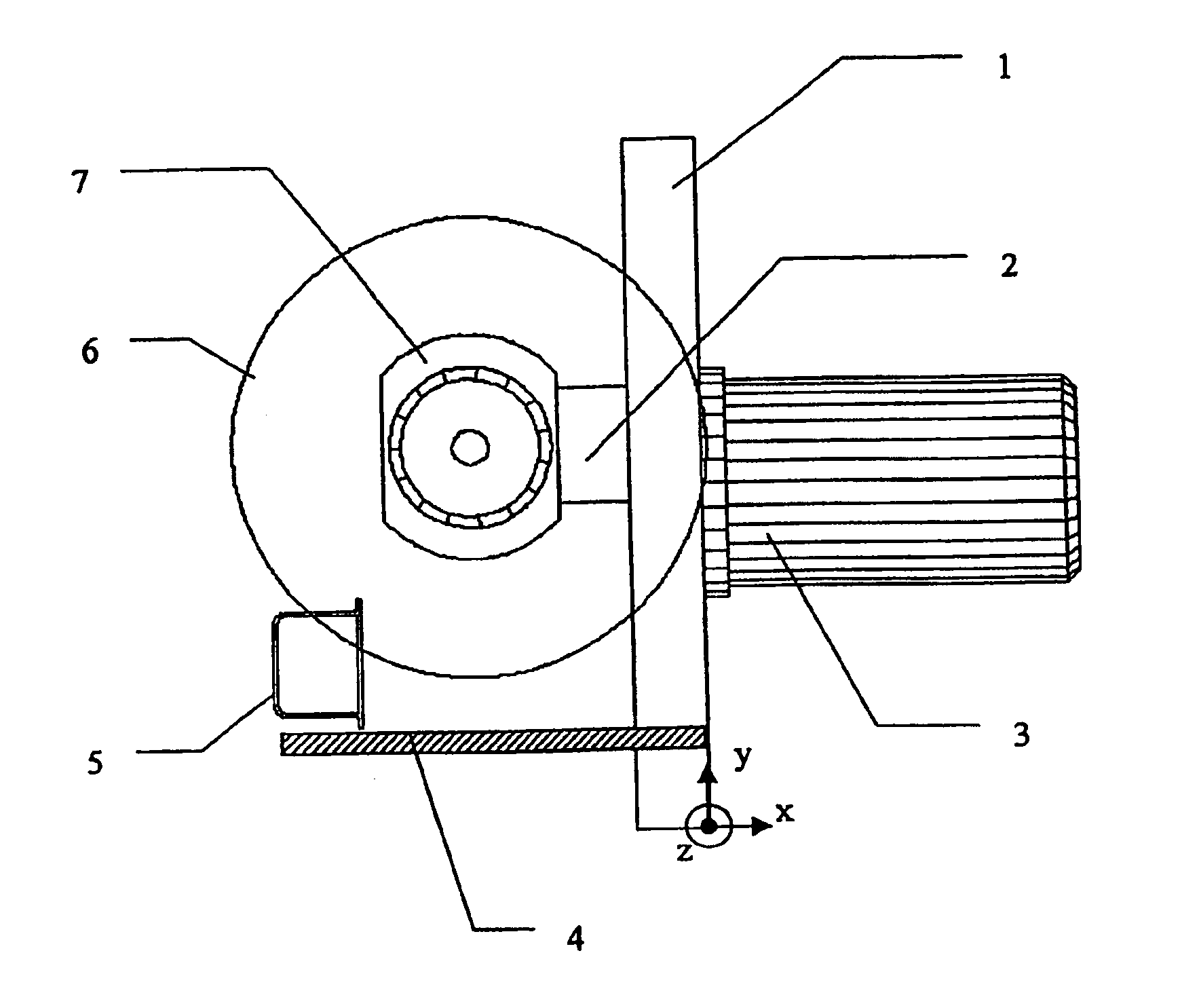
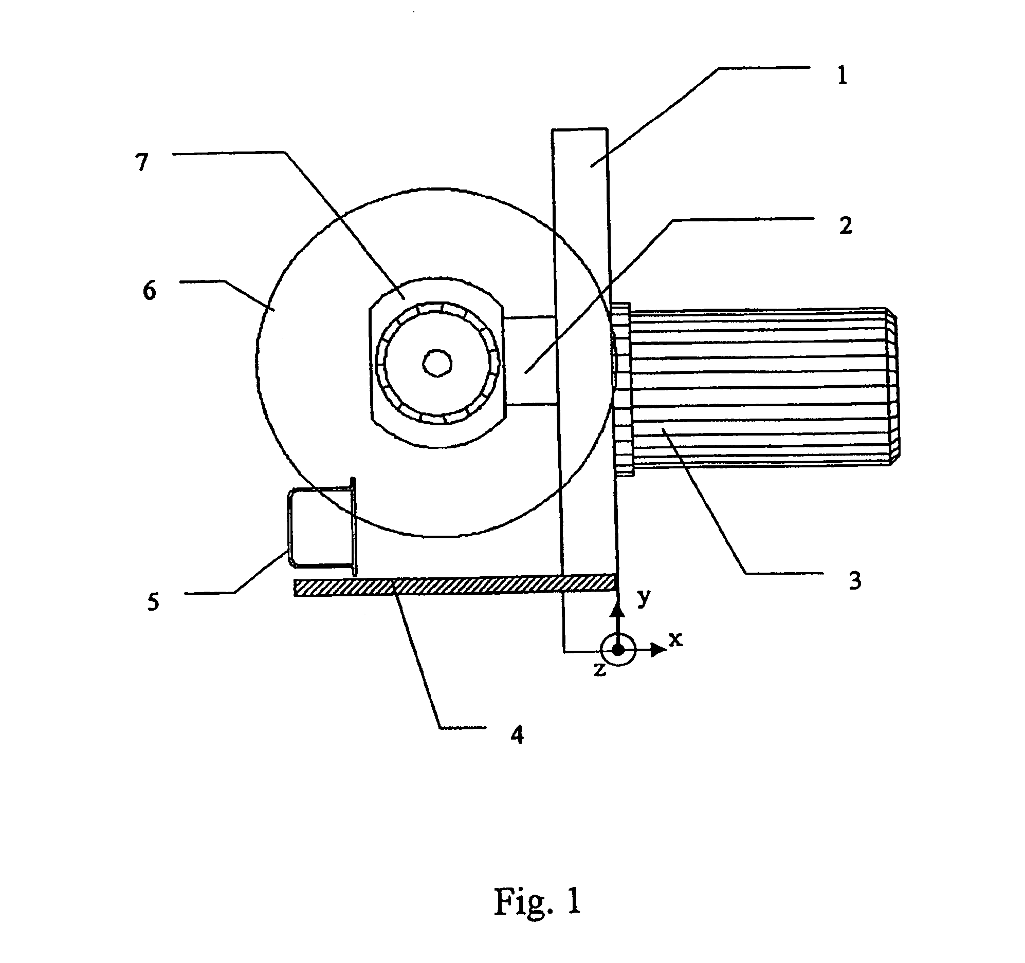
FIG. 1 is intended to illustrate the inventive method. The diagram is drawn in a Cartesian coordinate system, whose XY plane is parallel to the plane of the paper, and whose Z-axis is perpendicular to the XY plane. There is shown a robot arm 3, which at its end guides a parting tool configured as a saw and positioned close to an extruded profile section 5. Extruded profile section 5 is illustrated in cross section. Thus, in the press flow, it is being moved in the Z direction. In the present case, the hollow extruded profile section is made of an aluminum alloy. Alternatively, it could just as well be made of a magnesium alloy.

Mechanical parting of extrusion profile 5 takes place by saw blade 6, which is disposed in the XY plane and is powered in rotary motion via main drive 7. For parting of extrusion profile section 5, saw blade 6 is guided in Y direction through extruded profile section 5, while the saw is being moved along a feed axis 1 in the direction of the Y-axis. During cut...


PUM

PropertyMeasurementUnit
temperatureaaaaaaaaaa
speedaaaaaaaaaa

Abstract

A method for cutting a hollow extruded profile section into lengths in a press flow, wherein the extruded profile section is bent upon exit from the press either simultaneously with or directly after the forming extrusion process by a force acting thereon in a transversal manner in relation to the direction of the extruding press, and a force component acts as a traction of pressure force during the forming extrusion process on the cross-sectional area of the hollow-profile walls thus arising. The bent extruded profile section is cut in the press flow by the mechanical action of a saw, whereby force exerted on the extruded profile section during cutting is compensated by a supporting device arranged adjacent to the extruded profile section, so that deformation of the bent extruded profile section is prevented.

Description

FIELD OF THE INVENTIONThe present invention relates to a method for cutting an extruded profile section into lengths in the press flow of an extrusion machine. More precisely, it relates to a method for cutting an extruded profile section into lengths wherein the said profile section, after discharge from the press, is bent simultaneously with or immediately after the forming extrusion process by a force acting on the extruded profile section at right angles to the extrusion direction, one component of the force acting as a tensile or compressive force on the cross-sectional face of the resulting profile-section walls during the forming extrusion process.BACKGROUND OF THE INVENTIONIn industry, profiled workpieces are often produced on the basis of profile sections formed by extrusion of semifinished products. Depending on the material used in the semifinished product, extrusion takes place at a temperature that ensures plastic deformability. For example, aluminum or magnesium alloys...

Claims


Application Information

Patent Timeline
Patent Type & Authority Patents(United States)
IPC IPC(8): B21C23/02B21C23/12B21C23/00
CPCB21C23/12
Inventor BIRKENSTOCK, ALFJANDEWERTH, MARKUSHINZMANN, PAUL
Owner WKW ERBSLOEH AUTOMOTIVE GMBH
Why Eureka
Try Eureka