
Method of data transmission in a communication network with a ring configuration

a communication network and configuration technology, applied in the field of data transmission in a communication network with a ring configuration, can solve the problem of blocking the communication network for the other network subscribers, and achieve the effect of efficient utilization of data transmission capacity

Inactive Publication Date: 2005-03-01
HARMAN INT IND INC +1
View PDF7 Cites 18 Cited by
  • Summary
  • Abstract
  • Description
  • Claims
  • Application Information

AI Technical Summary

Benefits of technology

The present invention is therefore based on the object of providing a method of joint data transmission of digital source data and control data between data sources and data sinks that are subscribers of a uni-directionally operated communication network having a ring configuration which allows more efficient utilization of the data transmission capacity.
With the present invention it is possible to bring about a higher efficiency in the data transmission by making it possible to ensure that theoretically all the subscribers connected to the communication network can transmit data via the communication network simultaneously. In this case, the communication network can be utilized very effectively.
The present invention is suitable in particular for a communication network in which the sampling frequency of the connected subscribers is synchronized with the sampling frequency of the network. It would of course also be conceivable for these sampling frequencies not be synchronized with one another, but for the second sampling frequency to have any desired phase shift with respect to the first sampling frequency. This arbitrary phase shift, which may be, for example, 10% of the period of oscillation of the second sampling frequency, ensures greater flexibility in the data transmission. In this case, however, the subscriber receiving the data, for example a transceiver, should comprise means for data buffering.

Problems solved by technology

During this time, however, the communication network is blocked for the other network subscribers, as a result of which utilization capacity of the communication network is given away.

Method used


Image

  • Method of data transmission in a communication network with a ring configuration
  • Method of data transmission in a communication network with a ring configuration
  • Method of data transmission in a communication network with a ring configuration

Examples


Embodiment Construction

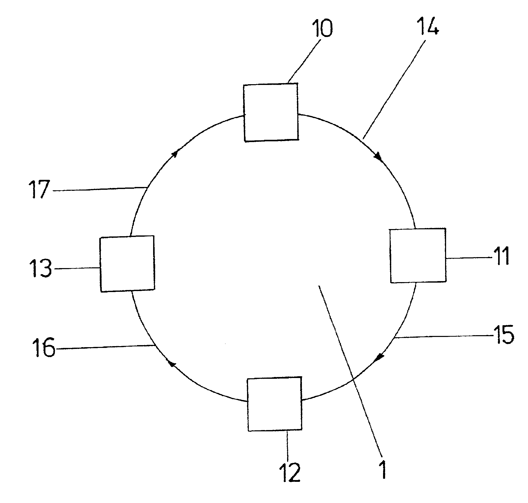
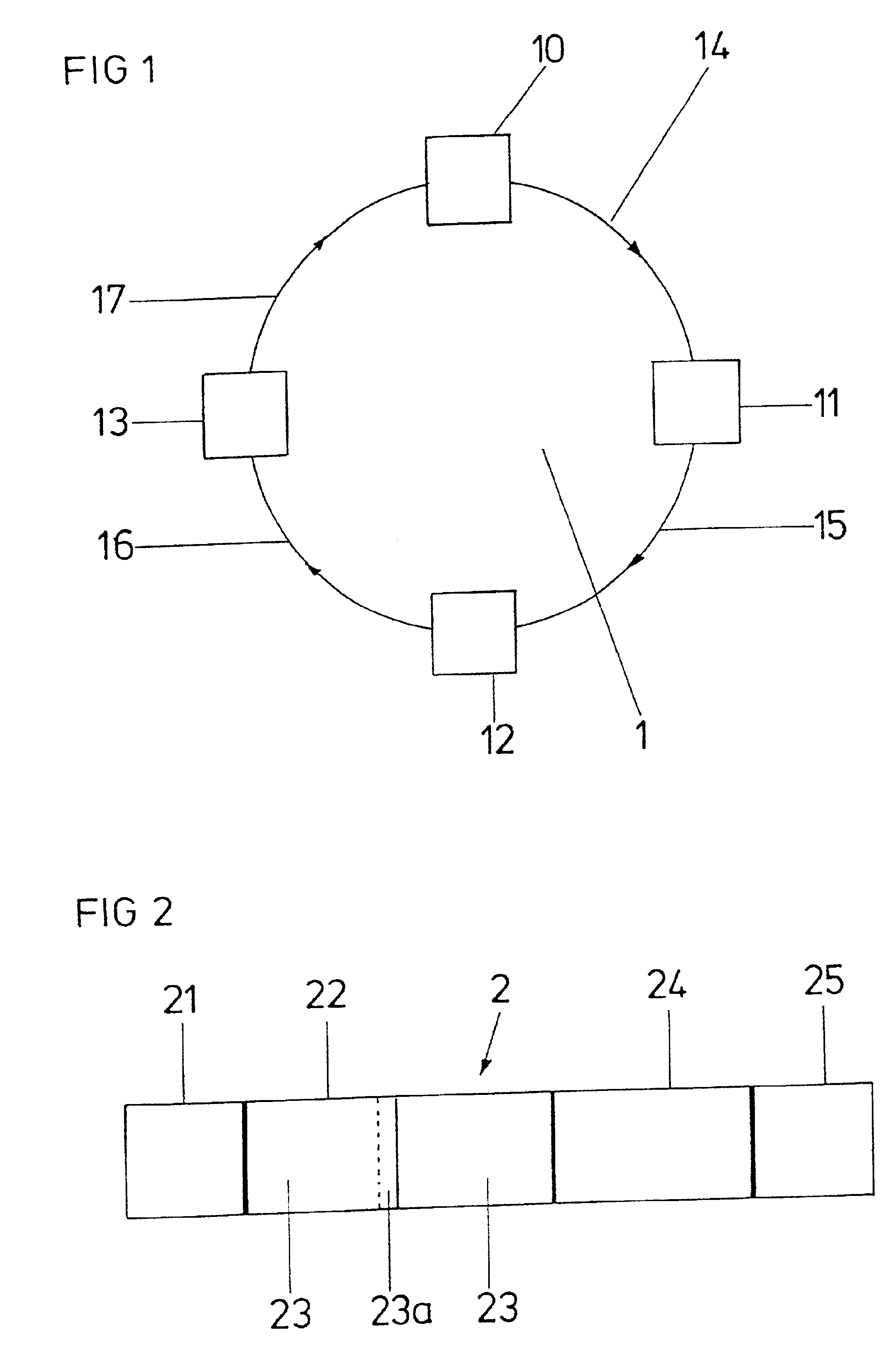
FIG. 1 shows a ring-shaped network 1, which in the present case is designed as a MOST network. The network 1 comprises four network subscribers 10, 11, 12, 13, one of the subscribers 10 being designed as a clock generator. The four subscribers 10, 11, 12, 13 are connected to one another in the form of a ring via uni-directionally operable data lines 14, 15, 16, 17 in such a way that a data stream can take place clockwise from one subscriber to the other 10, 11, 12, 13. The physical direction of the data transmission has been represented in FIG. 1 by arrows on the data lines 14, 15, 16, 17.

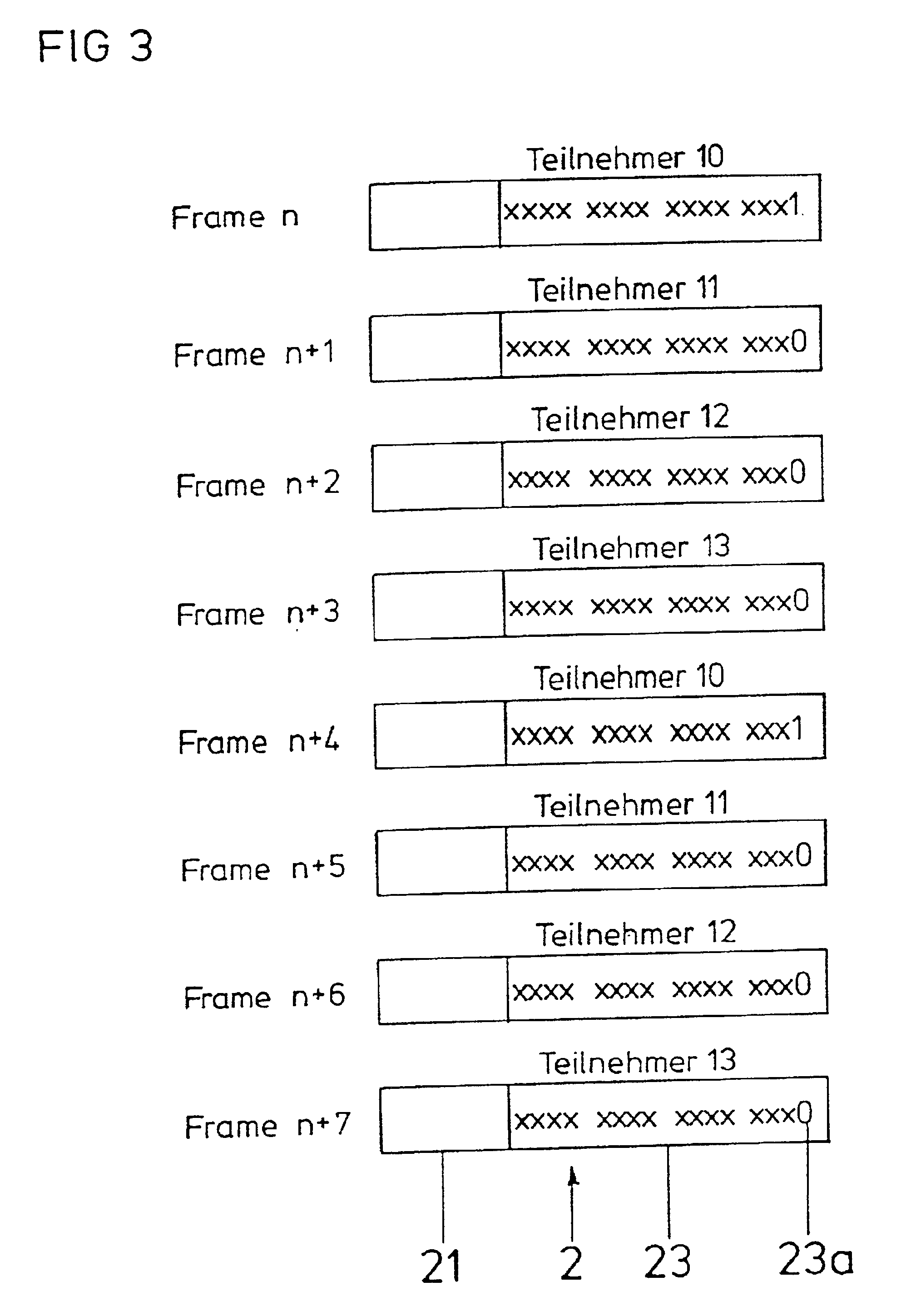
FIG. 2 shows the data transmission format used for the method according to the invention in a ring-shaped communication network corresponding to FIG. 1. In FIG. 2, a bit group, which is also referred to as a frame, is denoted by 2.

In the present exemplary embodiment, the bit group 2 comprises 64 bytes, that is to say 512 bits, which is an integral multiple of the lengths of bit groups in known tran...


PUM


Abstract

A method of joint data transmission of digital source data and control data is provided between data sources and data sinks which are subscribers of a uni-directionally operated communication network having a ring configuration, in which source data and control data are transmitted in a format which prescribes a clocked sequence of individual bit groups of the same bit width which are transmitted in a continuous data stream, in each case specific bit positions predetermined by the format are reserved, in which the subscribers sample data in each case with a first sampling frequency and the communication network samples data with a second sampling frequency, which is an integral multiple of the first sampling frequency, in which, within each bit group, at least one contiguous region with a predetermined number of bit positions can be reserved for source data and the contiguous region(s) in each case have a beginning and a defined length and are in each case assigned to a subscriber address, in which at least one contiguous region within a bit group is in each case assigned a significant bit position, which in the case of one of the subscribers is set to a first logic level and in the case of all the other subscribers is set to an opposed, second logic level.

Description

FIELD OF THE INVENTIONThe present invention is a method of data transmission in a communication network with a ring configuration. More specifically, the invention relates to a method of joint data transmission of digital source data and control data between data sources and data sinks, which are subscribers of a uni-directionally operated communication network having a ring configuration.BACKGROUND OF THE INVENTIONMethods of this type are used everywhere today where electronic and electrical devices of various types that are intended to exchange information with one another for the purpose of data communication are connected to one another, in a sometimes complicated way, by means of data lines and control lines. For instance, in the audio sector for example, the data communication between data sources networked with one another on the one hand—for example CD players, radio receivers, cassette recorders, microphones—and the data sinks connected to them on the other hand—for example...

Claims


Application Information

Patent Timeline
Patent Type & Authority Patents(United States)
IPC IPC(8): H04L12/407H04L12/413
CPCH04L12/42
Inventor STIEGLER, ANDREASSCHOEPP, HARALDBAEHREN, FRANK
Owner HARMAN INT IND INC
Learn More