
Squeeze evaluations that account for low frequency components, in a controller usable in a data handling system

Inactive Publication Date: 2005-03-01
SEAGATE TECH HDD HLDG +3
View PDF17 Cites 28 Cited by
  • Summary
  • Abstract
  • Description
  • Claims
  • Application Information

AI Technical Summary

Benefits of technology

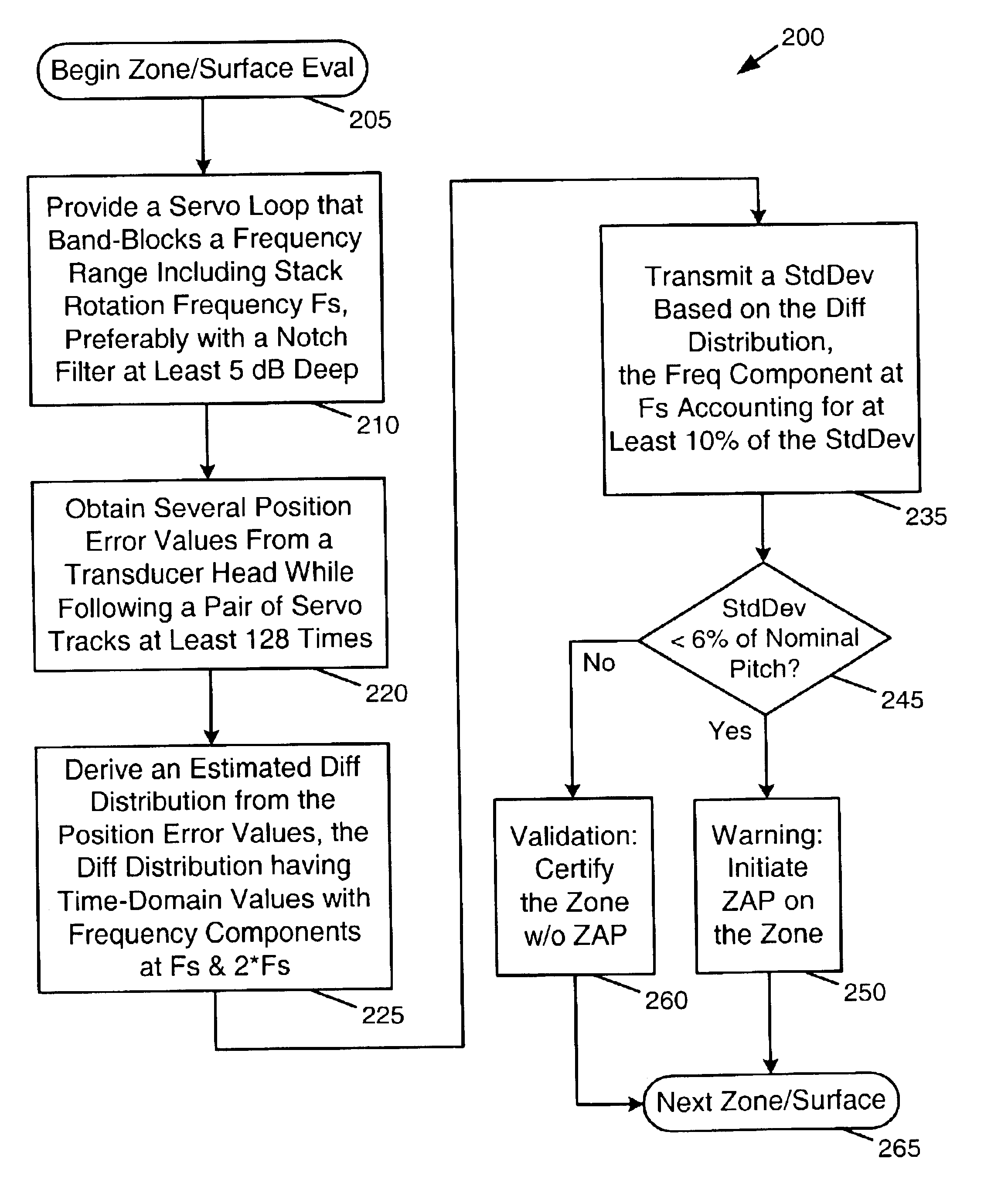
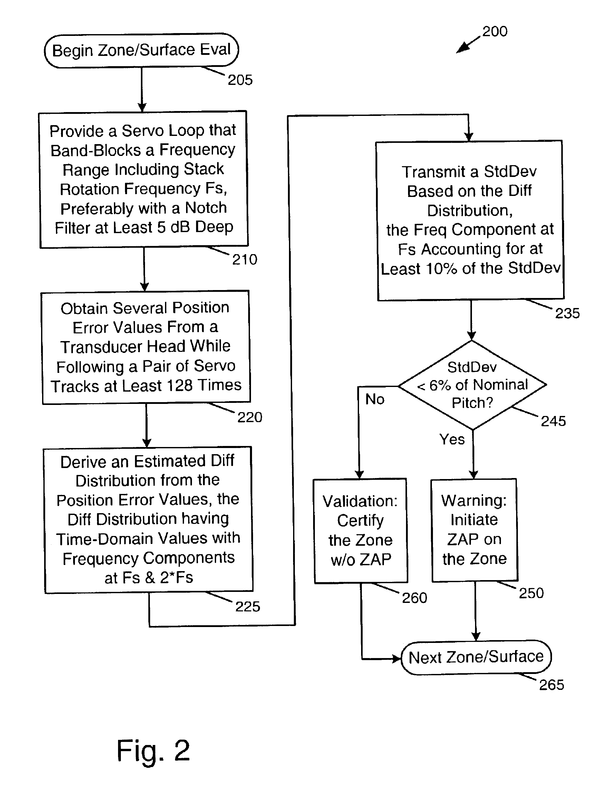
Rather than completely ignoring the low frequency components in an estimated difference distribution, the noise level in them is reduced by providing a servo feedback loop containing a band-block filter that blocks the control signal at a nominal rotation frequency, at least partially.

Problems solved by technology

However, two types of errors prevent heads from following this ideal path.
The first type of error is a written-in error that arises during the creation of the servo reference marks.
Written-in errors occur because the write head used to produce the servo reference marks does not always follow a perfectly circular path due to unpredictable pressure effects on the write head from the aerodynamics of its flight over the disc, and from vibrations in the gimbal used to support the head.
The track following errors can be caused by the same aerodynamic and vibrational effects that create written-in errors.
In addition, track following errors can arise because the servo system is unable to respond fast enough to high frequency changes in the path defined by the servo reference marks.
Written-in errors are often referred to as repeatable run-out errors because they cause the same errors each time the head passes along a track.
As track densities increase, these repeatable run-out errors begin to limit the track pitch.
Specifically, variations between the ideal track path and the actual track path created by the imperfectly-placed servo reference marks can result in a track interfering with (or “squeezing”) an adjacent track.
This is especially acute when a first written-in error causes a head to be outside of an inner track's ideal circular path and a second written-in error causes the head to be inside of an outer track's ideal circular path.
Unfortunately, ZAP and similar schemes are very expensive to implement on each data handling system.
One problem with squeeze evaluation systems is that the measurements they generate are not readily repeatable.
At higher track densities, this is not acceptable.

Method used


Image

  • Squeeze evaluations that account for low frequency components, in a controller usable in a data handling system
  • Squeeze evaluations that account for low frequency components, in a controller usable in a data handling system
  • Squeeze evaluations that account for low frequency components, in a controller usable in a data handling system

Examples


Embodiment Construction

Although the examples below show more than enough detail to allow those skilled in the art to practice the present invention, subject matter regarded as the invention is broader than any single example below. The scope of the present invention is distinctly defined, however, in the claims at the end of this document.

Numerous aspects of data storage device technology that are not a part of the present invention (or are well known in the art) are omitted for brevity, avoiding needless distractions from the essence of the present invention. For example, this document does not include specifics of how PES is manipulated in a conventional servo loop to control actuators that position transducer heads. Neither does it include specific methods for mounting fixed or removable discs into a stack. Specific techniques for implementing notch filters or other band-block filters are likewise omitted, typically being a matter of design choice to those of ordinary skill in servo controller design.

D...


PUM


Abstract

Position error values are obtained from a transducer head while following a plurality of servo tracks with a servo loop that band-blocks a frequency range that includes F, a nominal rotation frequency. An estimated difference distribution is derived from the position error values, the difference distribution having a first frequency component at a positive frequency ≦2*F. A scalar track squeeze magnitude indicator is derived from the estimated difference distribution so that the indicator to be transmitted depends on the frequency component.

Description

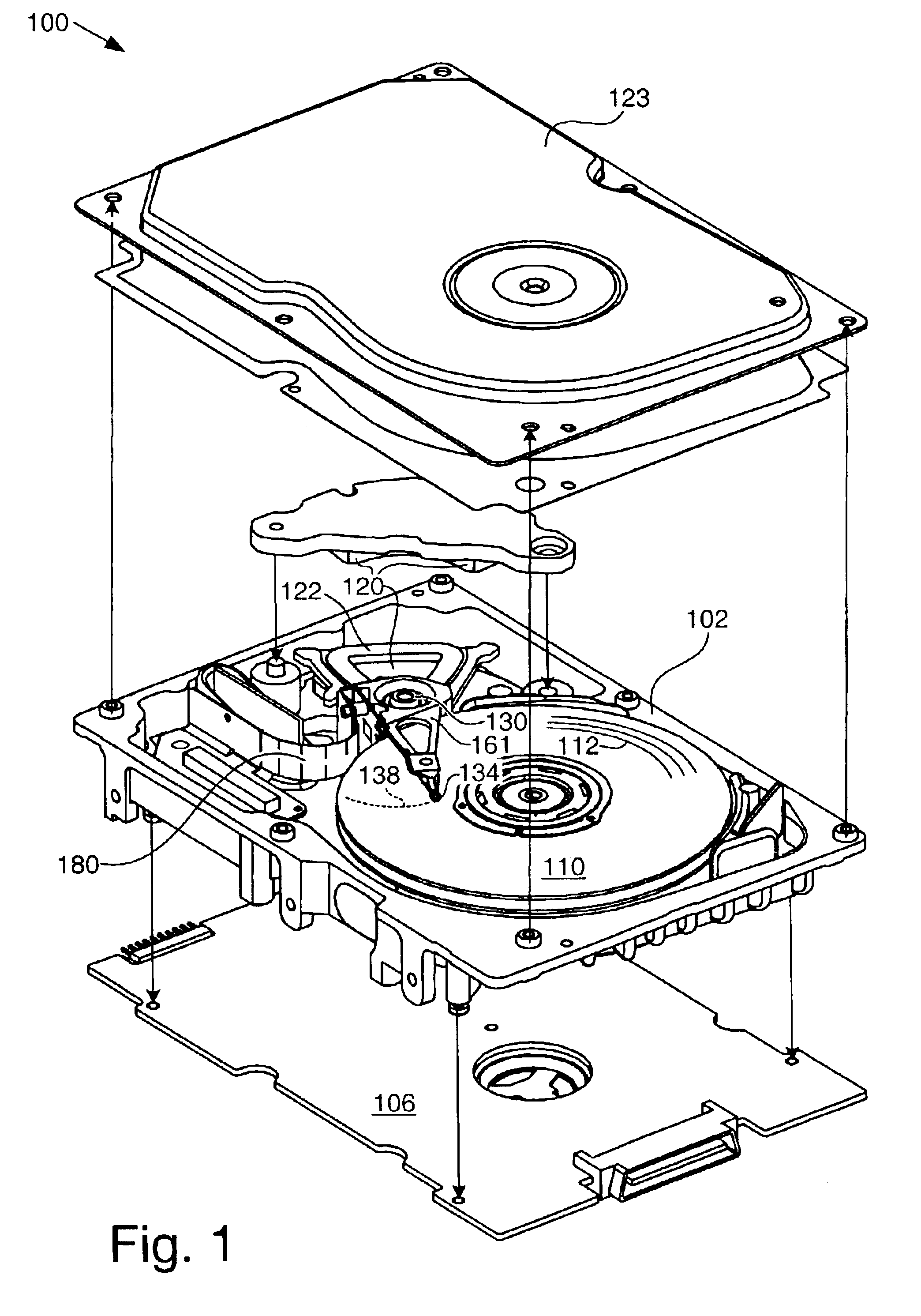
FIELD OF THE INVENTIONThis application relates generally to servo positioning systems and more particularly to evaluating devices that use them.BACKGROUND OF THE INVENTIONDisc drives read and write information along concentric tracks formed on discs. To locate a particular track on a disc, disc drives typically use embedded servo reference marks on the disc. These embedded fields are utilized by a servo subsystem to position a head over a particular track. The servo reference marks are written onto the disc when the disc drive is manufactured and are thereafter simply read by the disc drive to determine position.Ideally, a head following the center of a track moves along a perfectly circular path around the disc. However, two types of errors prevent heads from following this ideal path. The first type of error is a written-in error that arises during the creation of the servo reference marks. Written-in errors occur because the write head used to produce the servo reference marks do...

Claims


Application Information

Patent Timeline
IPC IPC(8): G11B5/596
CPCG11B19/045G11B5/59627
Inventor YANG, YONG Y.BI, QIANGLIU, XIONGLIM, CHOONKIAT
Owner SEAGATE TECH HDD HLDG
Learn More