
Arrangement of a heating layer for a high-temperature gas sensor

a technology of high-temperature gas and heating layer, which is applied in the direction of positive temperature coefficient thermistors, manufacturing tools, instruments, etc., can solve the problems of reducing the resistance of the heating conductor path, affecting the performance of the heating layer, and affecting the temperature of the heating layer

Inactive Publication Date: 2005-03-01
DAIMLER AG
View PDF29 Cites 18 Cited by
  • Summary
  • Abstract
  • Description
  • Claims
  • Application Information

AI Technical Summary

Benefits of technology

It is the object of the invention to arrange the heating conductor path(s) so that substantially the same temperature prevails at each location of the functional layer of the sensor. It is a further object of the invention

Problems solved by technology

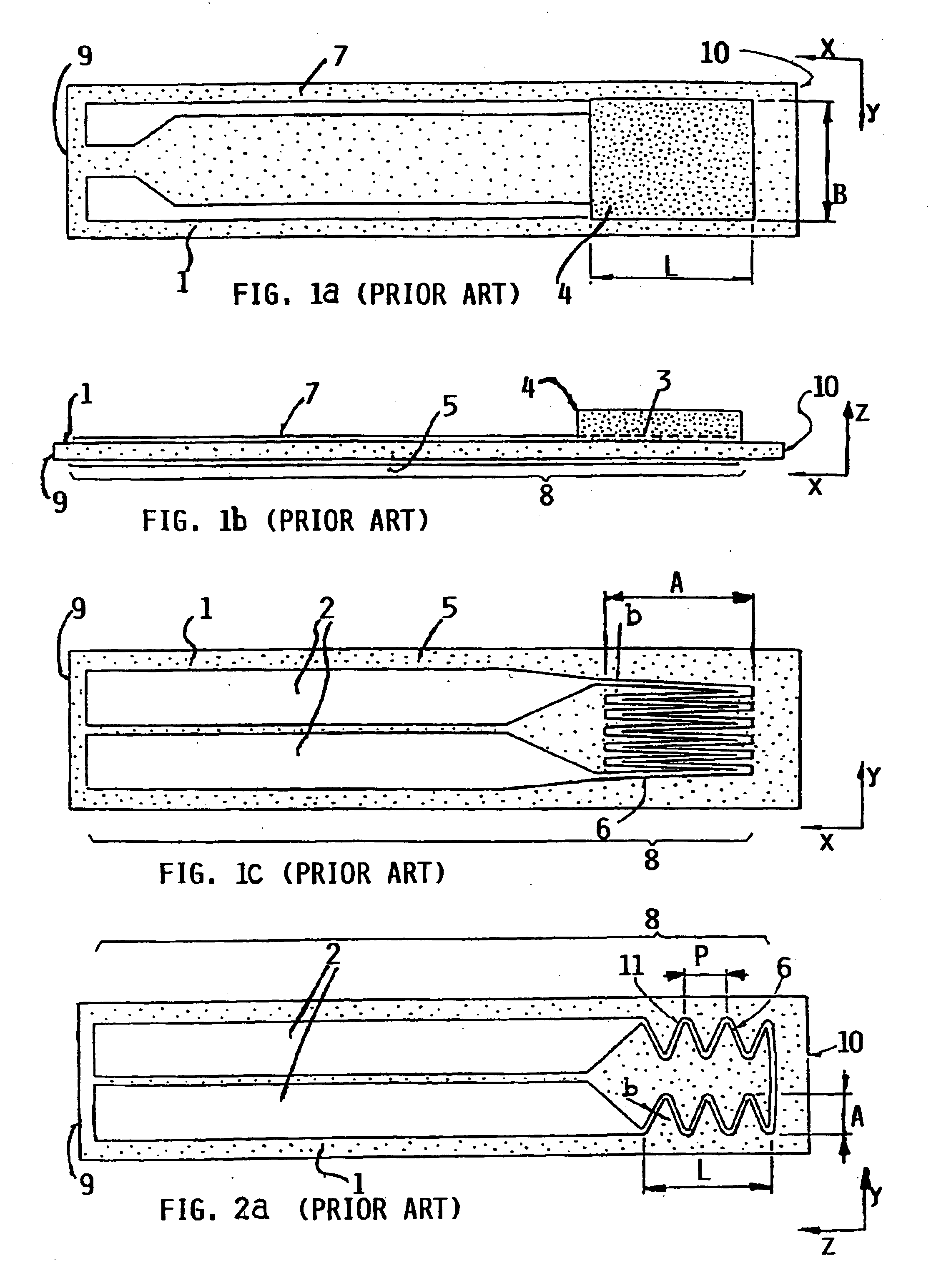
It is disadvantageous in all of the previously described arrangements, that a temperature gradient arises along the lengthwise axis x of the sensor, necessitated by the good thermal conductivity of the typically utilized Al2O3 substrate.
This temperature gradient is subject to very large fluctuations.
It is disadvantageous in this publication, however, that due to the parallel circuit connection, the resistance of the heating conductor paths is reduced so far or so low that it is no longer possible to establish a resistance in the range of several ohms for the same specific resistance of the heating conductor path resistance (generally platinum), because otherwise the layer thickness of the structure would have to become so thin that it could no longer be produced by thick layer or thick film technology.
It is disadvantageous in this publication, however, that the temperature profile of the sensor is not constant over the length L in the x-direction, and thus the heating resistance of the heating conductor path is only to be regarded as an average value over the entire range L. Therefore, a regulation can similarly only be achieved very inexactly therewith.
This is especially of disadvantage, if the temperature of the sensor housing changes strongly, as is the case, for example, in the exhaust gas of an automobile, because then the temperature gradient similarly strongly varies over the sensor chip, and thus RH can be allocated to no temperature of the functional layer.

Method used


Image

  • Arrangement of a heating layer for a high-temperature gas sensor
  • Arrangement of a heating layer for a high-temperature gas sensor
  • Arrangement of a heating layer for a high-temperature gas sensor

Examples


Embodiment Construction

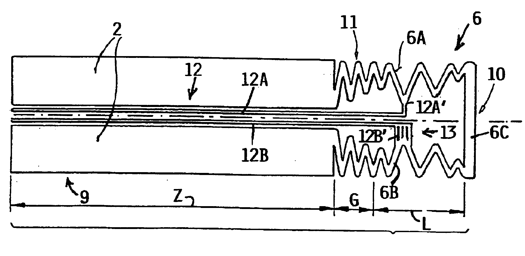
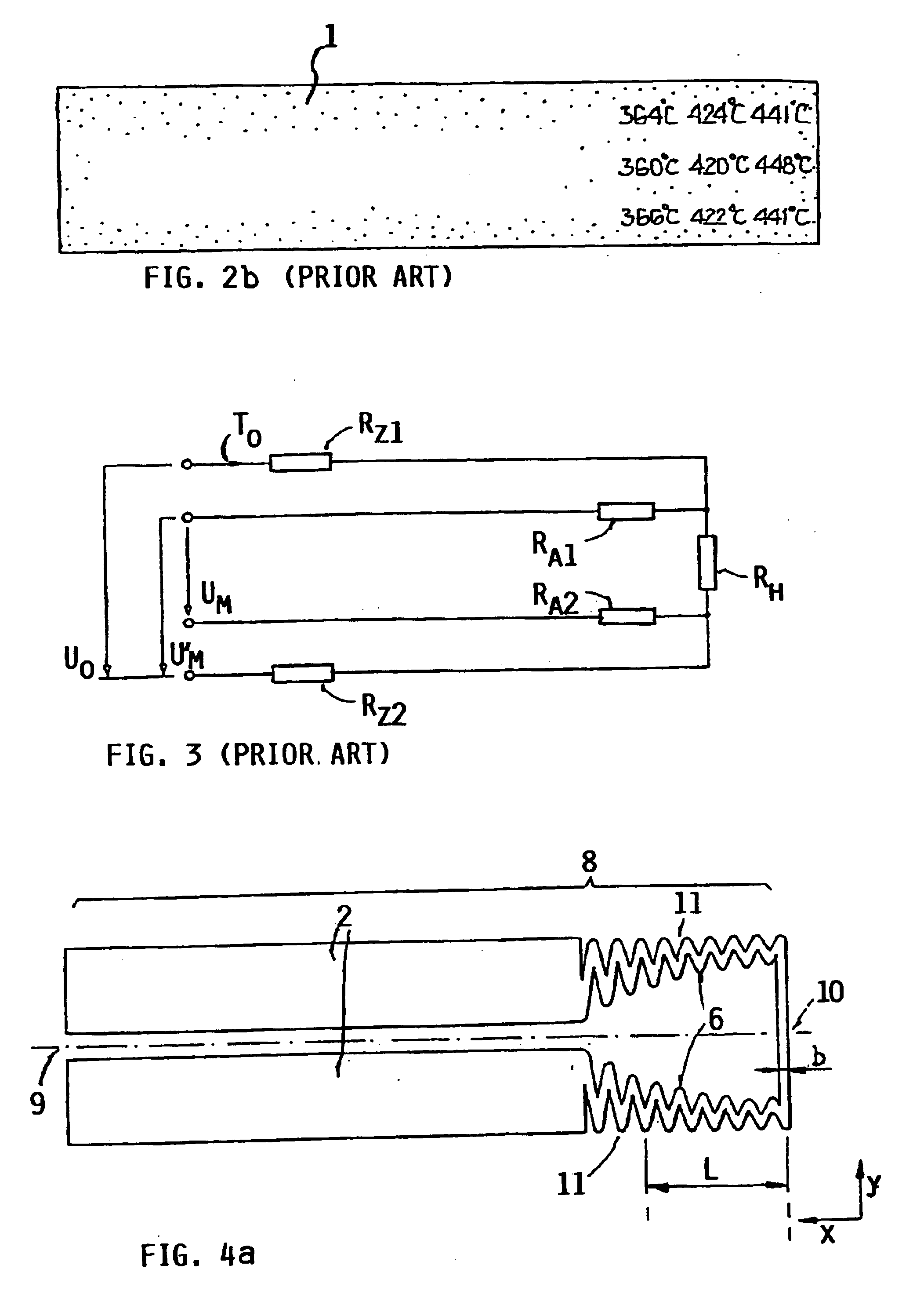
FIG. 4a shows a heating layer arrangement with a heating conductor path 6, of which the extending path or progression forms a meander-band, which, beginning on the electric power supply line part 2 also referred to herein as electric power supply conductors 2, first extends modulatingly on the one side parallel to the x-axis, and then extends in a straight line along the sensor tip parallel to the y-axis, and then again extends on the other side modulatingly parallel to the x-axis back to the electric power supply line part 2. In this context, the heating layer 8 was produced with a platinum thick film paste, which was applied by a screen printing technique onto an aluminum oxide substrate and thereafter was fired. For achieving a homogeneous temperature profile, the partial heating resistance in the x-direction was varied. The partial heating resistance is proportional to the quotient of the path length 1 and the width of the heating conductor path b relative to a path distance in ...


PUM

PropertyMeasurementUnit
Temperatureaaaaaaaaaa
Electric chargeaaaaaaaaaa
Currentaaaaaaaaaa

Abstract

The operating temperature of a gas sensor capable of sensing a gas or a gas composition at a high temperature, for example 1000° C. is maintained constant over the entire volume of a gas sensor layer or function layer (4) secured to a sensor carrier section of the gas sensor by supplying heat to the gas sensor layer (4) in such a way that varying heat dissipations in the sensor carrier section are compensated. For this purpose, an electrical heater for heating the gas sensor layer (4) has individual heater sections with different heating resistance values which depend on a spacing between any individual heater section and the tip of the sensor carrier section.

Description

FIELD OF THE INVENTIONThe invention relates to an arrangement of a heating layer for a high-temperature gas sensor, especially for sensing a gas or gas mixture at high temperatures.BACKGROUND INFORMATIONSensors that are used in the exhaust gas of a combustion engine must not only be high-temperature stable, but rather they must typically also be regulated to maintain a determined operating temperature, because both the temperature of the exhaust gas as well as the exhaust gas throughput are dependent on the operating state of the engine and vary strongly. Such sensors are operated at several hundred degrees Celsius. A typical example is the λ-sonde which can be operated at temperatures up to 1000° C.Other types of planar exhaust gas sensors, which are presently being produced by various manufacturers, consist of a structure as is shown in FIGS. 1a, 1b and 1c in various perspectives. In this context, FIG. 1a shows the top side of the sensor as a plan view, FIG. 1b shows the sensor in...

Claims


Application Information

Patent Timeline
IPC IPC(8): G01N27/406
CPCG01N27/4067
Inventor BISCHOF, MICHAELKESSLER, BURKHARDMOOS, RALFMUELLER, RALFMUELLER, WILLIPLOG, CARSTEN
Owner DAIMLER AG
Learn More