LED replacement for fluorescent lighting
a technology of led replacement and fluorescent lighting, which is applied in the direction of lighting support devices, coupling device connections, and power with built-in, can solve the problems of loss of the entire series circuit, and achieve the effect of reducing or eliminating any additional electrical components
- Summary
- Abstract
- Description
- Claims
- Application Information
AI Technical Summary
Benefits of technology
Problems solved by technology
Method used
Image
Examples
first embodiment
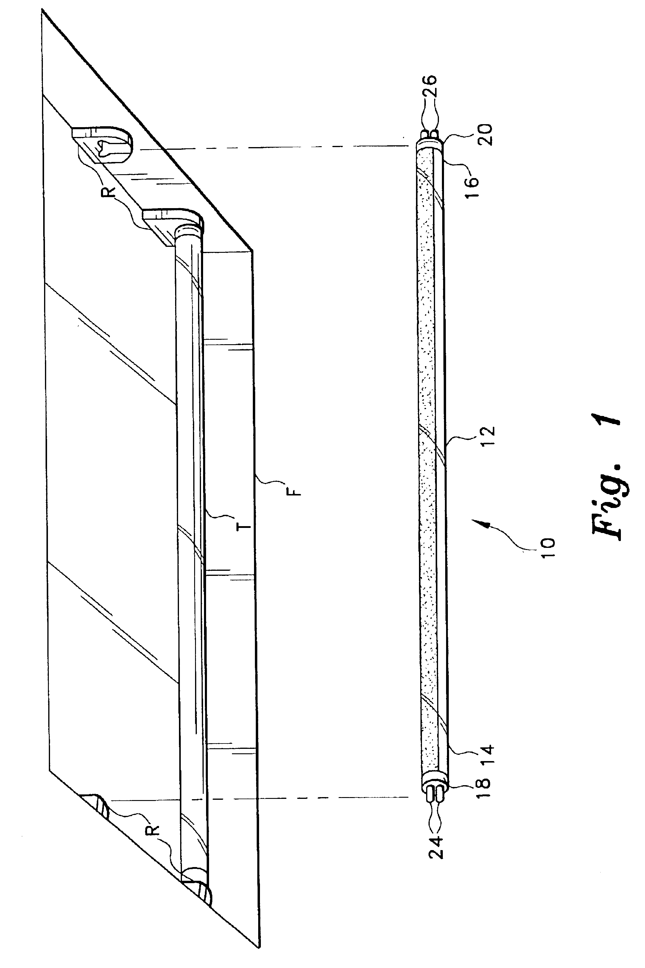
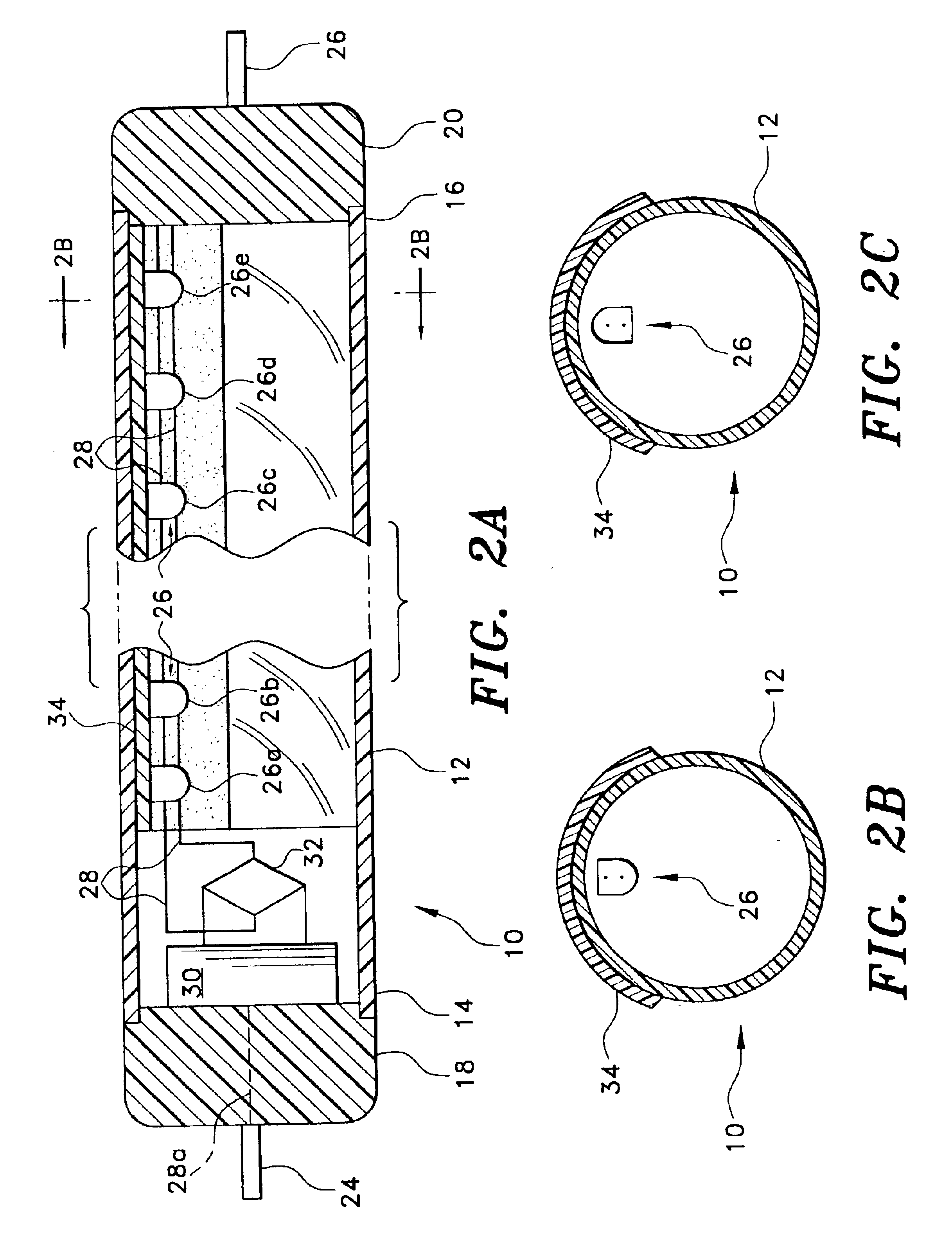
The present invention comprises various embodiments of a lighting element adapted for installation in a conventional fluorescent lighting fixture. The present lighting element contains one or more (preferably a plurality of) light emitting diodes (LEDs) therein, which provide the light emission from the device. FIG. 1 of the drawings illustrates the installation of a first embodiment LED replacement lighting device 10, within an existing conventional fluorescent lighting fixture F. The fluorescent lighting fixture F is adapted to receive one or more elongate, tubular fluorescent lighting tubes T therein, with the tubes T being secured between opposed electrical receptacles R. While the fluorescent fixture F illustrated in FIG. 1 comprises an overhead fixture containing two straight, elongate tubes or lighting elements, it will be seen that the present LED replacements for fluorescent lighting are adaptable to virtually any configuration of fluorescent lighting element, e.g., U-shape...
second embodiment
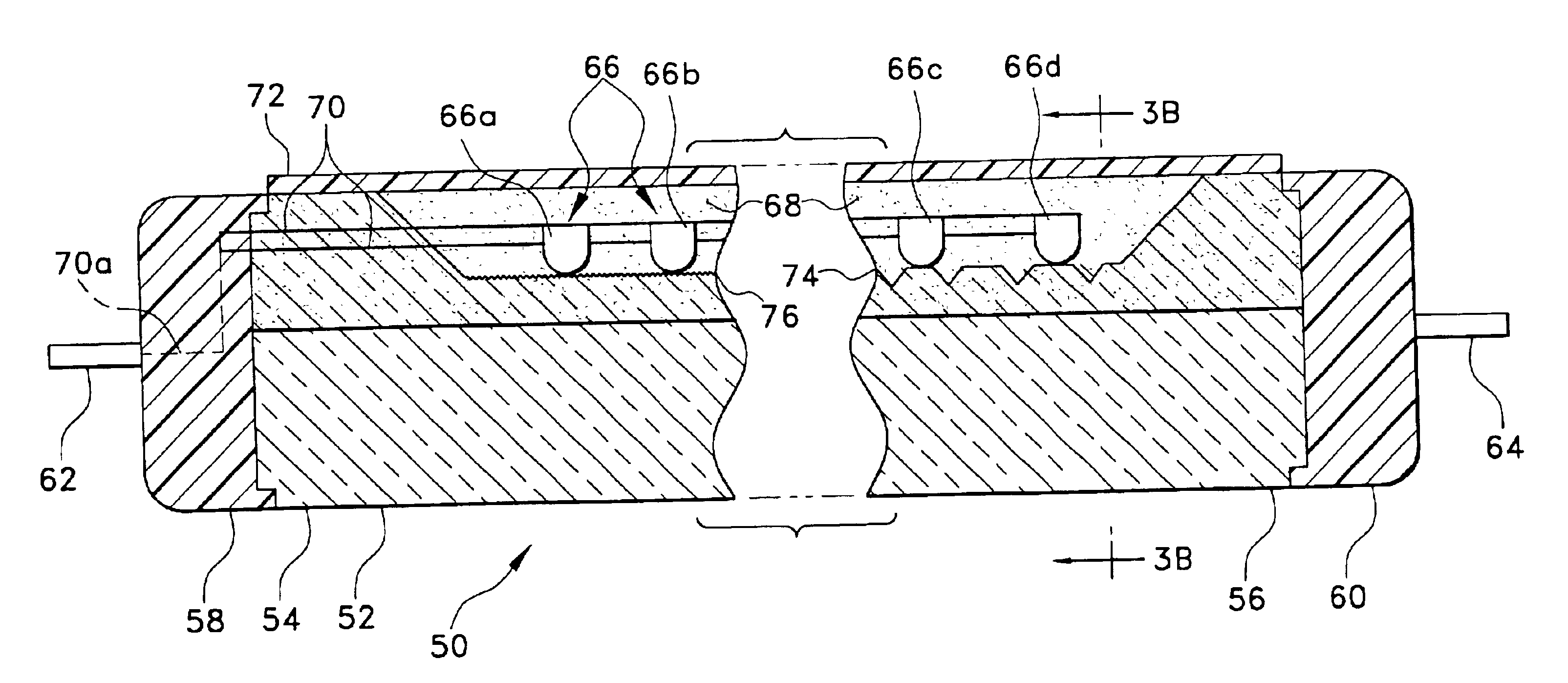
FIGS. 3A and 3B illustrate the present invention, comprising lighting device 50. The elongate element of the light 50 is formed as a solid, rigid, transparent or translucent rod 52 of suitable material (plastic, glass, etc.), having opposite first and second ends, respectively 54 and 56. Each end is equipped with an end cap, respectively 58 and 60, with corresponding fluorescent fixture receptacle connector pins, respectively 62 and 64, extending from each end cap 58 and 60. Excepting the fact that the elongate element comprises a solid rod 52 rather than a hollow tube, as in the embodiment of FIGS. 2A and 2B, the basic configuration of the lighting element 50 is much like that of the lighting element 10 of FIGS. 2A and 2B, being adapted for installation in a conventional fluorescent lighting fixture.
A series of white or colored light emitting diodes 66, comprising LEDs 66a, 66b, 66c, etc., is provided for the lighting device 50. However, the LEDs 66 are installed in a depression 68...
embodiment 50
As in the light 10 of FIGS. 2A and 2B, the light 50 may also include some form of reflective coating 72 (reflective paint, tape, sheathing, etc.) applied along a portion of the circumference of the rod 50, and extending over the LEDs within their receptacle or receptacles 68. In addition, some form of light diffusing means is desirable in the solid rod embodiment 50 of the present invention, and may comprise a series of V-shaped or other shaped notches 74 (shown to the right side in FIG. 3A, or a relatively fine grating 76 (to the left, in FIG. 3A), or other irregularities disposed over the surface of the LED receptacle(s) 68, so long as the means provided is sufficient to diffuse the light as desired.
FIG. 3C represents an alternative configuration of the LED replacement light 50 illustrated in FIGS. 3A and 3B. The directional nature of the light output of the LEDs of the light 50 of FIGS. 2A and 2B, with their downward and outward orientation, may result in the light being distribu...
PUM
 Abstract
Description
Claims
Application Information
 - R&D
- Intellectual Property
- Life Sciences
- Materials
- Tech Scout
- Unparalleled Data Quality
- Higher Quality Content
- 60% Fewer Hallucinations
Browse by: Latest US Patents, China's latest patents, Technical Efficacy Thesaurus, Application Domain, Technology Topic, Popular Technical Reports.
© 2025 PatSnap. All rights reserved.Legal|Privacy policy|Modern Slavery Act Transparency Statement|Sitemap|About US| Contact US: help@patsnap.com


