
Throttle devices having motors supported by elastic, metallic support members

Inactive Publication Date: 2005-03-01
AISAN IND CO LTD
View PDF15 Cites 28 Cited by
  • Summary
  • Abstract
  • Description
  • Claims
  • Application Information

AI Technical Summary

Benefits of technology

Therefore, one object of the present teachings is to provide improved throttle devices that have improved supports for preventing motor vibration.
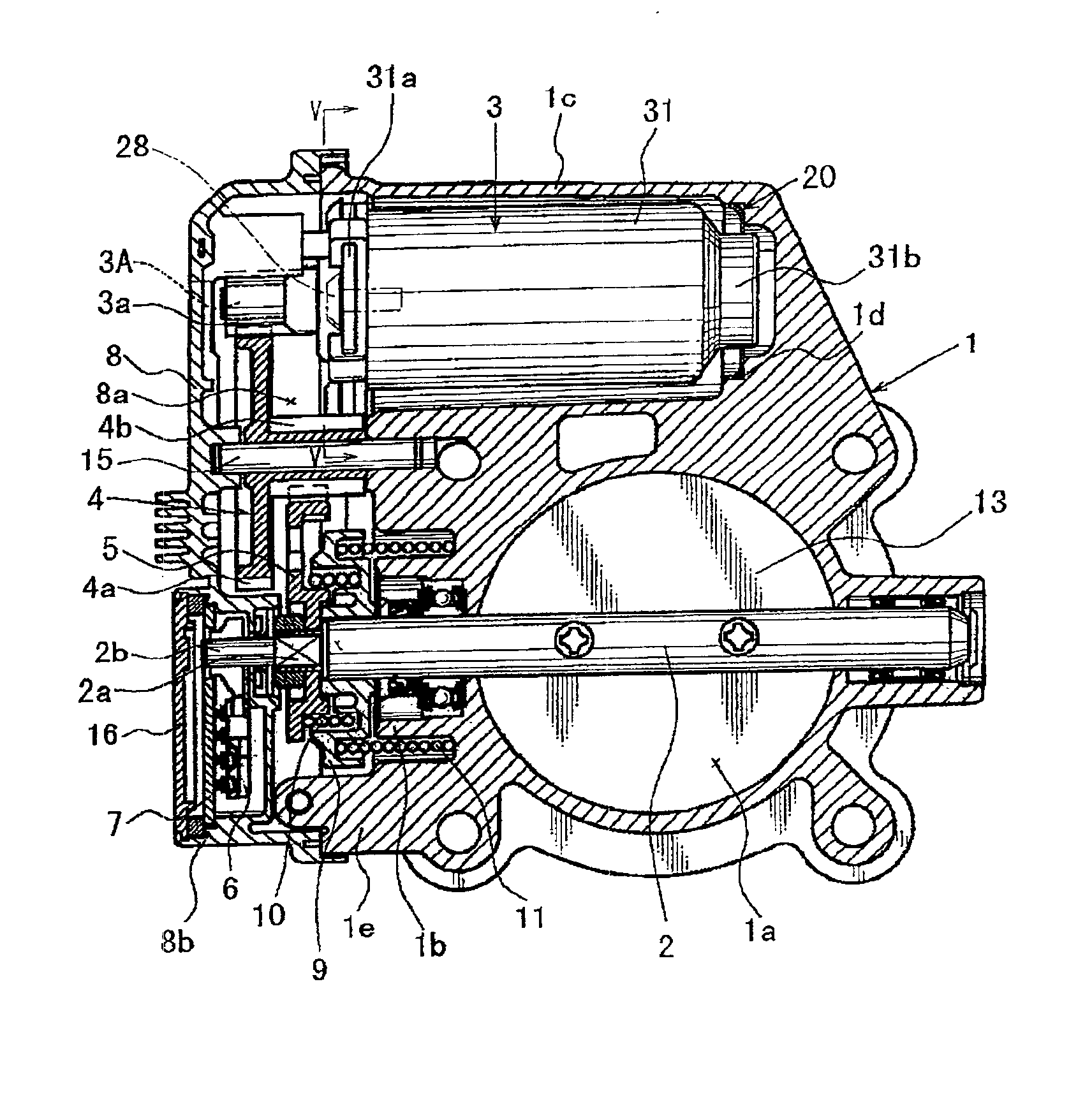
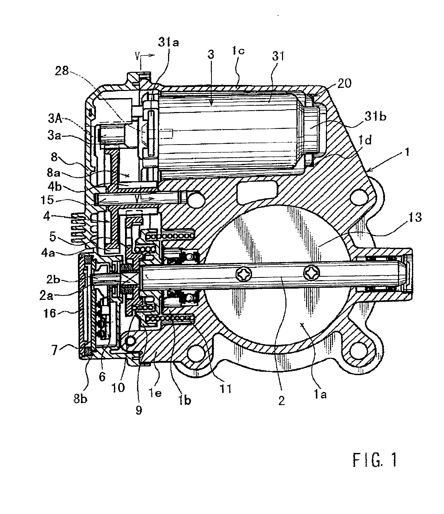
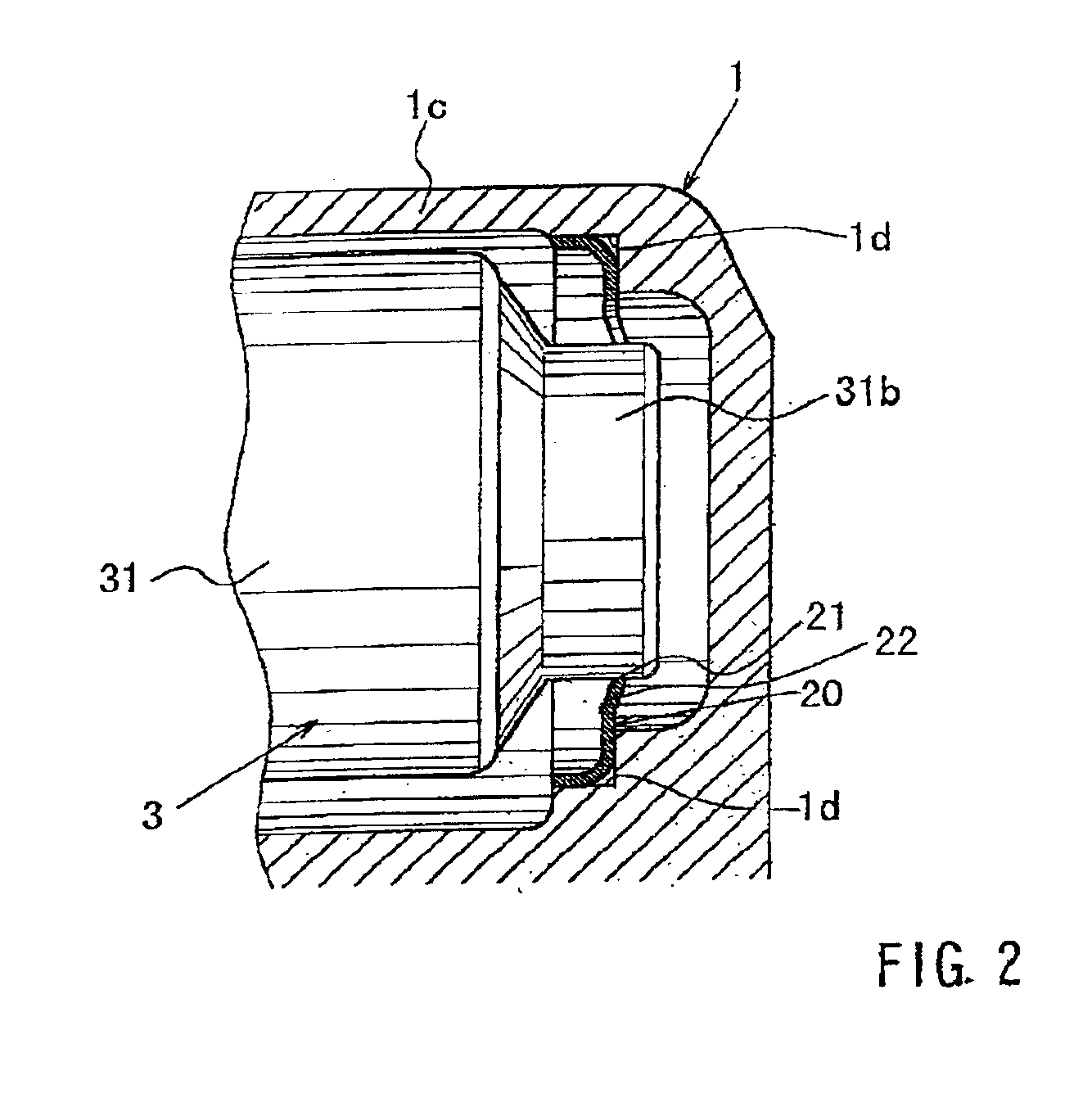
In one of the aspect of the present teachings, throttle devices are taught that may include a throttle body. A first support and a second support may be disposed within the throttle body (or a motor case defined within the throttle body) and preferably support a motor along the longitudinal direction of the motor. The motor may be coupled to a throttle valve and the motor may control the opening position of the throttle valve with respect to an air intake passage defined within the throttle body. Preferably, at least one of the first and second supports is made from an elastic material. In this case, it is possible to prevent or substantially reduce motor vibration along the diametrical direction of the motor.
In addition or in the alternative, at least one of the first and second supports may be made of material that has relatively high heat conductivity, such as a metallic material. In this case, heat generated by the motor during operation may be reliably conducted or transferred to the throttle body and then may be dissipated to the outside environment. Therefore, the motor may be reliably cooled during operation and prevented from failing due to overheating.
According to another aspect of the present teachings, at least one of the first and second support may be a spring, such as a leaf spring. Therefore, any vibrations transmitted from an outside vibration source, e.g. an automobile engine, to the motor may be dampened by the spring. Thus, in this aspect, the motor can be further prevented from vibrating during operation. In addition, if a metallic leaf spring is utilized as the first and / or second support, the vibration properties of the metallic leaf spring preferably will not be degraded due to motor heat, thereby further preventing motor vibrations during operation. Furthermore, heat from the motor may be reliably conducted or transferred to the outside environment in order to effectively cool the motor during operation.

Problems solved by technology

Therefore, any vibrations transmitted from an outside vibration source, e.g. an automobile engine, to the motor may be dampened by the spring.

Method used


Image

  • Throttle devices having motors supported by elastic, metallic support members
  • Throttle devices having motors supported by elastic, metallic support members
  • Throttle devices having motors supported by elastic, metallic support members

Examples


Embodiment Construction

In one embodiment of the present teachings, a throttle device may include a throttle body that defines an air intake passage. A throttle valve may be disposed so as to open and close the air intake passage. A motor may rotatably drive the throttle valve and the motor may have a longitudinal axis. A first support may support a first side of the motor along the longitudinal direction of the motor. A second support may support a second side of the motor along the longitudinal direction of the motor. Consequently, the motor may be supported from both sides along the longitudinal direction of the motor. Due to this arrangement, vibrations along the diametrical direction of the motor relative to the throttle body can be reduced. Optionally, at least the first support may support the motor such that the motor cannot move both along its longitudinal direction and its diametrical direction.

In another embodiment of the present teachings, the second support may be made of material that has rel...


PUM


Abstract

A throttle device with a throttle body and first and second supports supporting a motor for controlling the opening position of the throttle of a valve. The first and second supports support the motor from both sides of the motor in the longitudinal direction. At least one of the first and second supports may also elastically support the motor, and may be a metallic leaf spring disposed within the throttle body.

Description

This application claims priority to Japanese application serial number 2001-145025, which application is hereby incorporated by reference herein in its entirety.BACKGROUND OF THE INVENTION1. Field of the InventionThe present invention relates to throttle devices and control devices for controlling the opening and closing of a throttle valve. For example, such throttle valves may be utilized to control the amount of air that is supplied to an engine, such as an automobile engine. More particularly, the present invention relates to throttle devices having a motor for driving the throttle valve, the motor being resiliently and elastically supported within the throttle body.2. Description of the Related ArtJapanese Laid-open Patent Publication No. 5-180006 generally discloses a known throttle device that includes a throttle body, a throttle valve and a motor. The throttle body defines an air intake passage and the throttle valve is disposed within the air intake passage. The motor serve...

Claims


Application Information

Patent Timeline
IPC IPC(8): F02D11/10F16K31/04F16K1/22F02D9/10F02D9/02
CPCF02D11/10F16K31/043F16K1/221F05C2201/021
Inventor SAKURAI, TORUNISHITANI, TSUTOMUKITAMURA, SUNAO
Owner AISAN IND CO LTD
Learn More