
Local degraded area repair and restoration component for pressure retaining items

a technology for repairing and restoring components and pressure retaining items, which is applied in the direction of manufacturing tools, mechanical equipment, metal working equipment, etc., can solve the problem of completely encapsulating the material of unacceptable pressure retaining items, and achieve the effects of alleviating or eliminating, eliminating or minimizing the use of weld joint backing strips, and being sa

Inactive Publication Date: 2005-03-01
MANZON PAUL STEPHEN
View PDF16 Cites 17 Cited by
  • Summary
  • Abstract
  • Description
  • Claims
  • Application Information

AI Technical Summary

Benefits of technology

The objective of the invention is to provide a simple, safe, cost effective, method of repairing a pressure retaining item. A further objective is to provide a method of repair that alleviates or eliminates many, if not all, of the negative aspects of some current repair methods, including repair methods referred to as the “flush patch repair” or the “weld build-up repair” methods (the “flush patch repair” or the “weld build-up repair” methods are described in the previous section of this Specification entitled “BACKGROUND OF THE INVENTION”).
It is believed that the invention alleviates many of the negative aspects of the “flush patch repair” or “weld build-up repair” current common methods of repair, and offers several advantages. Negative aspects of the “flush patch repair” or “weld build-up repair” methods of repair that are alleviated by the invention and several advantages of the invention over the “flush patch repair” or “weld build-up repair” include but are not limited to the following:
The invention:1. by it use and attachment may not require removal of the pressure retaining item from service2. by it use and attachment may not require cutting out of the pressure retaining item local material degraded areas3. by it use and attachment may only require minimal preparation of the pressure retaining item material for weld attachment of the invention in comparison to the “flush patch repair” or the “weld build-up repair” methods.4. by it use and attachment may eliminate or minimize use of weld joint backing strips in the attachment weld between a pressure retaining item and the invention which then by not using said weld joint backing strip would substantially reduce or eliminate in most cases a requirement to impose or consider a reduction in the pressure retaining item factor of safety as applicable to a pressure retaining item's pressure retention or structural integrity.5. by it use and attachment may eliminate or minimize use of weld joint backing strips in the attachment weld between a pressure retaining item and the invention which then by not using said weld joint backing strip would substantially reduce or eliminate an attachment with a geometrical configuration that would contribute to acceleration of existing areas of erosion or corrosion or lead to new areas that would be subjected to erosion or corrosion at rates in excess of those that existed prior to the attachment of the invention.6. by it use and attachment may eliminate exposure of personnel to lethal or hazardous fluid contents such as chemical, gas, or radioactive fluid contents of a pressure retaining item.7. by it use and attachment may eliminate the potential for damage to internal parts of pressure retaining items such as damage to tubes of heat exchangers. Damage to tubes of heat exchangers would necessitate repair of tubes or plugging of tubes with an associated loss in equipment performance and economic loss.8. by it use and attachmen

Problems solved by technology

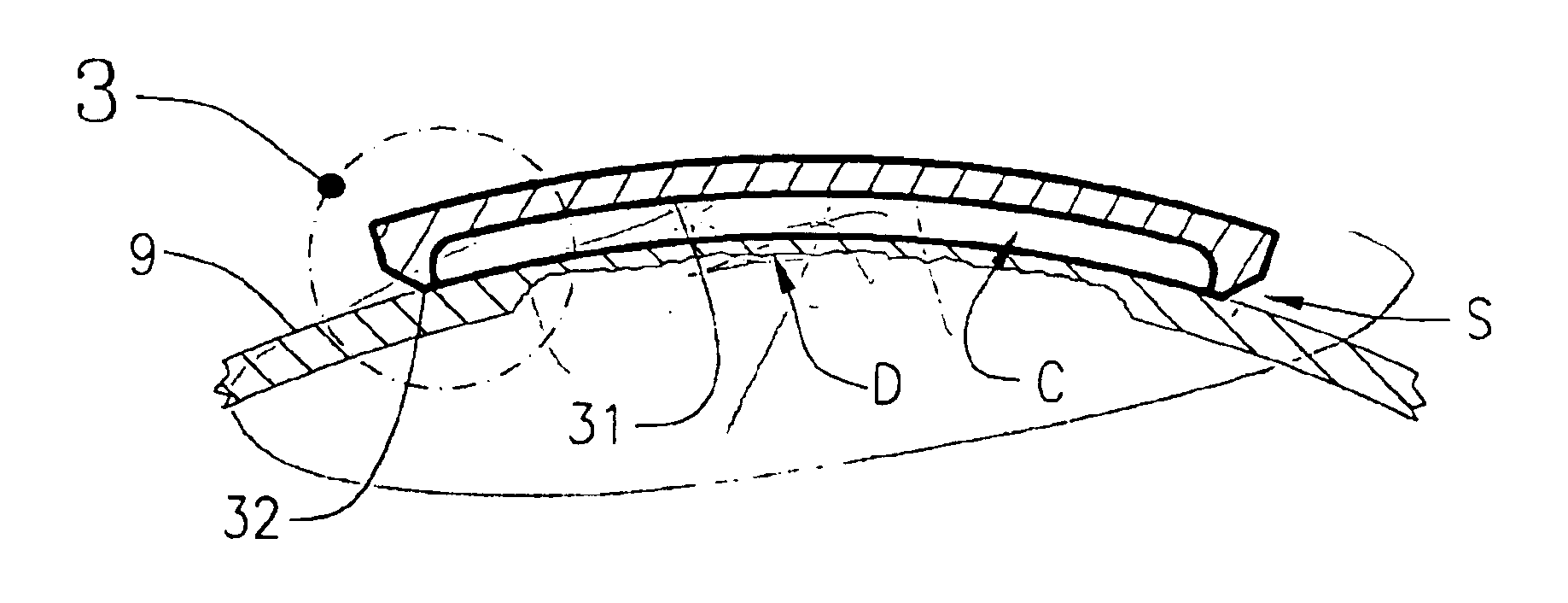
Thus a section of unacceptable pressure retaining item material is completely encapsulated by the cap.

Method used


Image

  • Local degraded area repair and restoration component for pressure retaining items
  • Local degraded area repair and restoration component for pressure retaining items
  • Local degraded area repair and restoration component for pressure retaining items

Examples


Embodiment Construction

General

The “Local Degraded Area Repair and Restoration Component for Pressure Retaining Items (Pressure Maintenance Cap)”, hereinafter referred to as “the invention”, is a component used to repair and restore the structural and pressure retaining integrity of pressure retaining items whose pressure retaining material of construction has been subjected to material degradation. The invention consists of a single component of metallic material that is welded to the surface of a pressure retaining item. The invention is welded directly over a section of the pressure retaining item where material degradation has occurred. Installation of the invention on a pressure retaining item can return the structural and pressure retaining integrity, and allowance for corrosion and / or erosion of a pressure retaining item to equal or better conditions than the original as-designed or as-constructed condition of the pressure retaining item.

Construction of Invention

The invention is shown in sample inve...


PUM

PropertyMeasurementUnit
Thicknessaaaaaaaaaa
Pressureaaaaaaaaaa
Areaaaaaaaaaaa

Abstract

What is new in the art to which my invention pertains is that it allows for a repair or restoration of a pressure retaining item that has local material degradation to an acceptable state of condition for continued operation without the need to cut out the degraded section of material or breach the pressure boundary of a pressure retaining item. Common methods of repair include removal of degraded or affected material section and replacement with a new section of equivalent material by joining the new material to an existing item at a location of adequate thickness using full or complete penetration welds. This type of repair may be referred to in the industry as a “flush patch repair”. An additional type of repair where a section of material degradation may be localized is a “weld build-up repair’ wherein weld metal is deposited onto the existing area of affected material to return the material to its original thickness. Both “flush patch repair” and weld build-up repair” methods require breaching of the pressure boundary integrity of a pressure retaining item to implement a repair. The invention does not require breaching a pressure boundary.

Description

BACKGROUND OF THE INVENTIONThis application is for a component that is used to repair or restore structural and pressure retention integrity of pressure retaining items. Pressure retaining items include but are not limited to items referred to as pressure vessels, tanks, towers, boilers, reactors, heat exchangers, pipe, pumps, and valves. Pressure retaining items are generally constructed of metallic material. Methods of construction of pressure retaining items include welded construction, bolted construction, riveted construction, and a completed pressure retaining item may be constructed using one or various combinations of welded, bolted, or riveted construction. Various industry Codes and Standards provide construction, operation, and inspection requirements pertaining to pressure retaining items in the United States. These include Codes and Standards published by various organizations including but not limited to the American Society of Mechanical engineers (ASME), American Nat...

Claims


Application Information

Patent Timeline
IPC IPC(8): F16L55/18
CPCF16L55/18Y10T29/49732
Inventor MANZON, PAUL STEPHEN
Owner MANZON PAUL STEPHEN
Learn More