
Stationary clothes drying apparatus with jet nozzles

a drying apparatus and stationary technology, applied in the field of stationary drying, can solve the problems of limited mass transfer, increase in overall heat and mass transfer rate, etc., and achieve the effects of increasing heat transfer rate, enhancing and uniform heat transfer, and improving performance of stationary drying devices

Inactive Publication Date: 2005-03-01
WHIRLPOOL CORP
View PDF23 Cites 70 Cited by
  • Summary
  • Abstract
  • Description
  • Claims
  • Application Information

AI Technical Summary

Benefits of technology

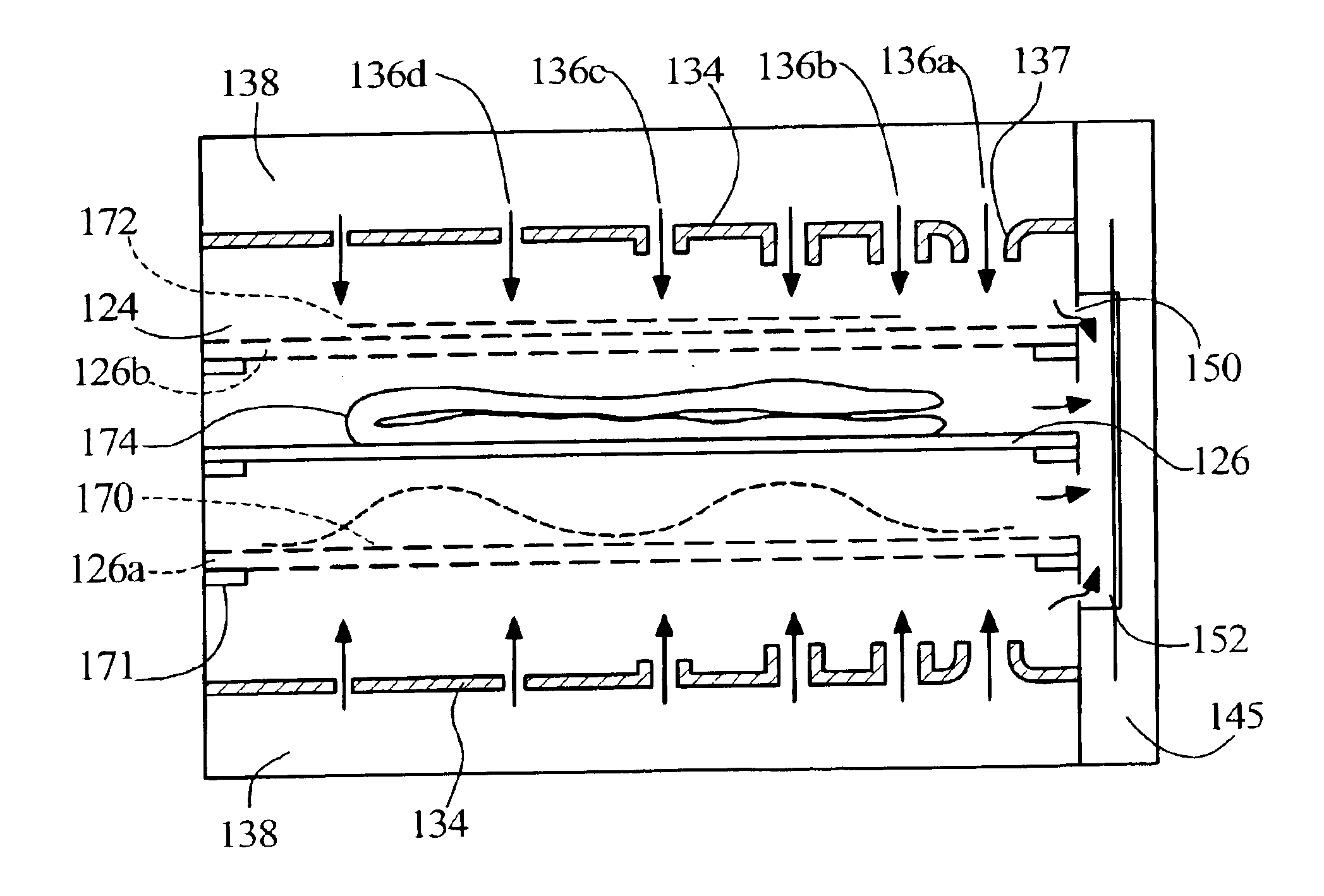
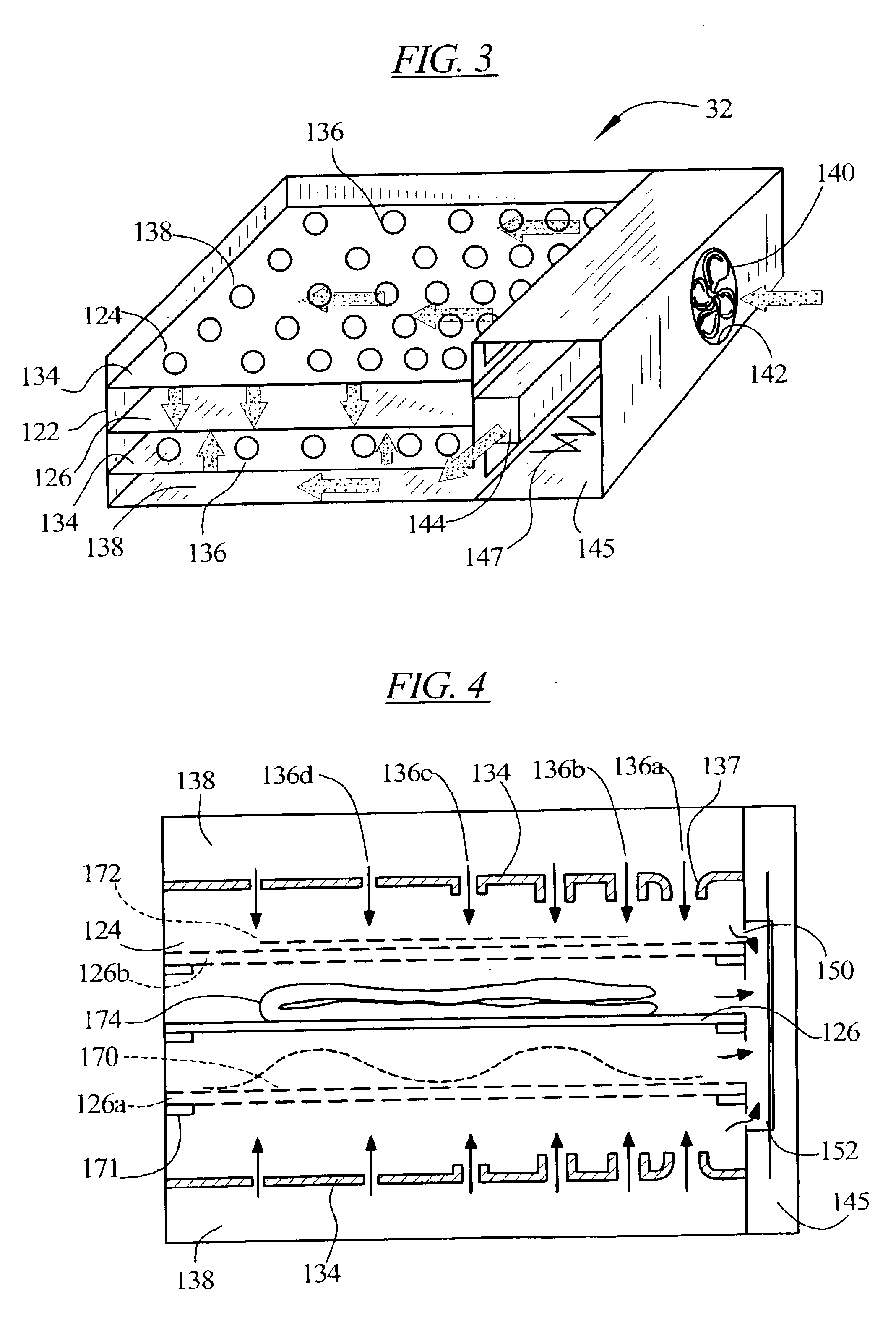
The present invention provides for improved performance in stationary drying devices through the use of jet impingement to increase the heat transfer rate (such as by double) in comparison to conventional parallel flow convection for the same fan / blower capacity. The present invention provides enhanced and uniform heat transfer which improves the free water evaporation rate. The present invention provides arrangements for both hanging and laying objects so that air flow is effective for both types of items.
The thermal boundary layer developed in conventional parallel flow convection resists heat and mass transfer. Jet impingement significantly reduces the boundary layer near the jet and increases the overall heat and mass transfer rate. In addition, where conventional parallel flow convection for drying occurs over a significant length, mass transfer becomes limited due to higher water vapor concentrations in the bulk flow. In the case of jet impingement, flow of equal capacity for evaporation can be provided over a large area of the object being dried. Although the spent flow in the case of jet impingement may be limited in water vapor capacity, lateral transfer of water within the fabric will usually minimize the spent flow effect.
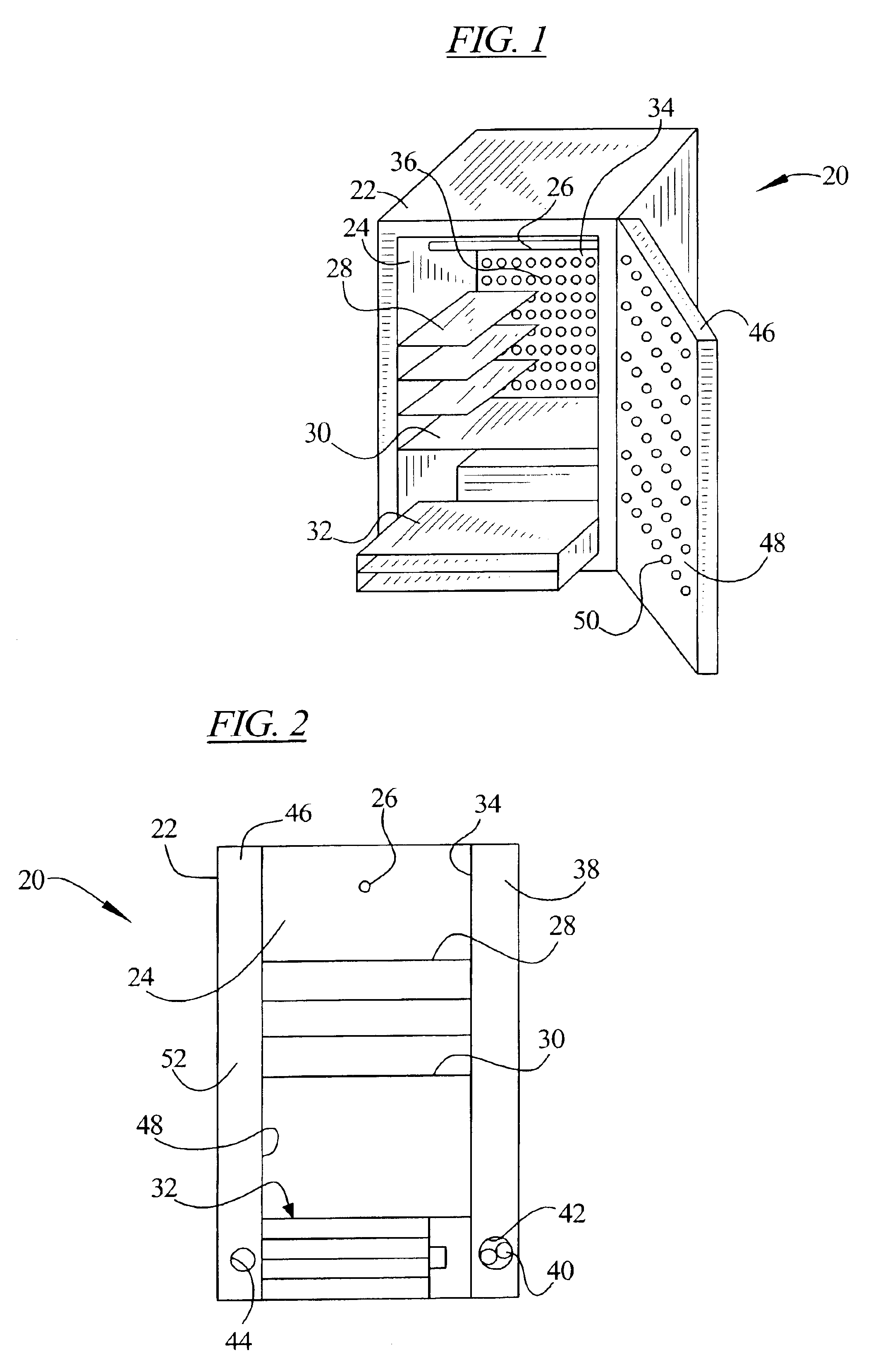
In an embodiment of the invention, a stationary clothes dryer is provided which comprises a housing enclosing a space and a clothes support located within the space. The clothes support remains stationary during the drying operation, but may be movable, such as a drawer, to increase the ease of introducing and removing clothing articles to be dried. An air moving device is also provided for generating an air flow through the space from an air inlet to an air outlet. An air distributor mechanism is provided which comprises a distribution plenum positioned between the air inlet and the clothes support, with a plenum wall having a plurality of perforations or nozzles therein, the perforations / nozzles being sized, shaped and arranged so as to provide jets of air against the clothes support and to equalize an air flow distribution over said clothes support.

Problems solved by technology

Jet impingement significantly reduces the boundary layer near the jet and increases the overall heat and mass transfer rate.
In addition, where conventional parallel flow convection for drying occurs over a significant length, mass transfer becomes limited due to higher water vapor concentrations in the bulk flow.

Method used


Image

  • Stationary clothes drying apparatus with jet nozzles
  • Stationary clothes drying apparatus with jet nozzles
  • Stationary clothes drying apparatus with jet nozzles

Examples


Embodiment Construction

A stationary dryer incorporating the principles of the present invention can be practiced in many different embodiments. Some of these embodiments are shown and described herein, however, the present invention is not limited to the particular embodiments contained in this description.

The term stationary dryer is meant to cover drying devices in which the articles to be dried remain relatively stationary during the drying process. The dryer itself may be movable to different locations and various components of the dryer may be movable, particularly when the articles to be dried are being placed into or removed from the dryer. While such a device could be used to dry a wide variety of articles, for the purposes of providing an enabling disclosure of the best mode of the invention, embodiments are described below for drying clothing or other fabric articles, however, the invention is not limited to such specific uses.

In FIG. 1 a stationary dryer which may be useful for drying clothes i...


PUM


Abstract

A stationary dryer, useful as a clothes dryer, is provided comprising a housing enclosing a space and a stationary clothes support located within the space. An air moving device is provided for generating an air flow through the space from an air inlet to an air outlet. An air distributor mechanism comprising a distribution plenum is positioned between the air inlet and the clothes support, with a plenum wall having a plurality of perforations therein. The perforations are sized, shaped and arranged so as to provide jets of air against the clothes support and to equalize an air flow distribution over the clothes support.

Description

BACKGROUND OF THE INVENTIONThe present invention relates to stationary drying, such as for clothes drying, and particularly to a stationary drying apparatus including an air flow directed against the clothes to be dried.Significant percentages of items that are washed are not dried in a tumble dryer. Estimates of percentages are as high as 40%. These items are typically dried hanging in ambient air or, if the danger of stretching exists, dried laying flat in ambient air. When drying in this manner, free convection is the primary mechanism of heat transfer. Free convection also carries away evaporated water in support of the necessary mass transfer.Drying rates can be doubled or tripled in comparison to free convection when common fans or blowers are used to provide conventional parallel flow forced convection heat transfer. Heat transfer rates may also be greatly increased for conventional forced convection, however fan / blower cost will typically rise exponentially with increased he...

Claims


Application Information

Patent Timeline
IPC IPC(8): D06F58/10
CPCD06F58/10
Inventor MEYER, ROBERT W.
Owner WHIRLPOOL CORP
Learn More