
Diagnostics for industrial process control and measurement systems

a technology of industrial process control and measurement system, applied in the field of field devices operating in the process control and measurement industry, can solve the problems of system failure, process communication loop operating in such processing environment is typically energy-limited, and field devices in such environment are also generally energy-limited

Inactive Publication Date: 2005-02-22
ROSEMOUNT INC
View PDF109 Cites 101 Cited by
  • Summary
  • Abstract
  • Description
  • Claims
  • Application Information

AI Technical Summary

Benefits of technology

The patent describes a device that can measure certain characteristics of a digital control system and provide a diagnosis of its condition based on those measurements. This can help detect any faults or deterioration in the system by comparing the measured characteristics to predicted or historical data. The device can measure various characteristics such as voltage, current, or temperature, and can provide a detailed analysis of the overall health of the control system.

Problems solved by technology

Industrial processing environments that require intrinsic safety compliance provide an added challenge for electrical instrumentation and automation of the process control system since such environments may contain flammable or explosive vapors.
Accordingly, process communication loops operating in such processing environments are typically energy-limited.
Field devices in such environments are also generally energy limited as well.
Process communication loops that have the potential for higher level signals that could spark under fault conditions are often not permitted to pass through or connect to equipment in a flammable processing environment.
For example, should a single device fail and begin to draw too much energy, the signaling levels on the process communication loop could collapse thereby inhibiting all communication over the loop and effectively causing the system to fail.

Method used


Image

  • Diagnostics for industrial process control and measurement systems
  • Diagnostics for industrial process control and measurement systems
  • Diagnostics for industrial process control and measurement systems

Examples


Embodiment Construction

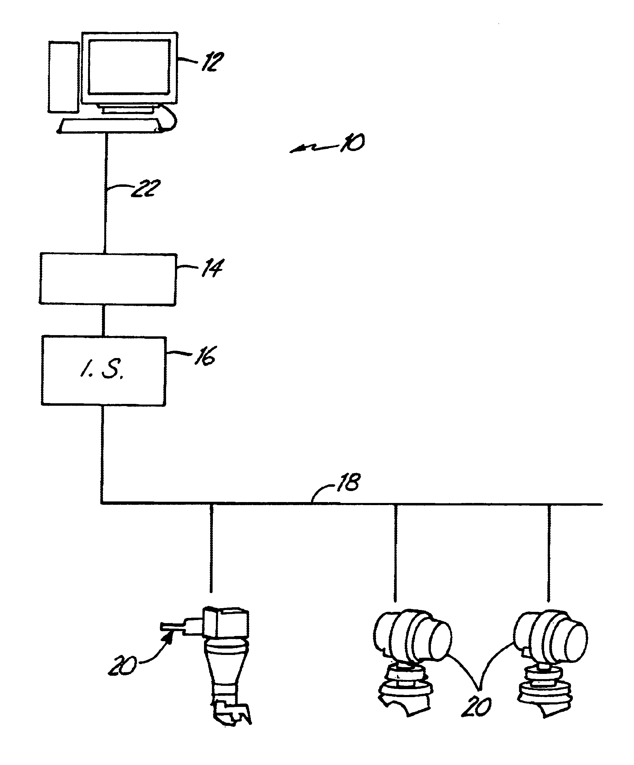
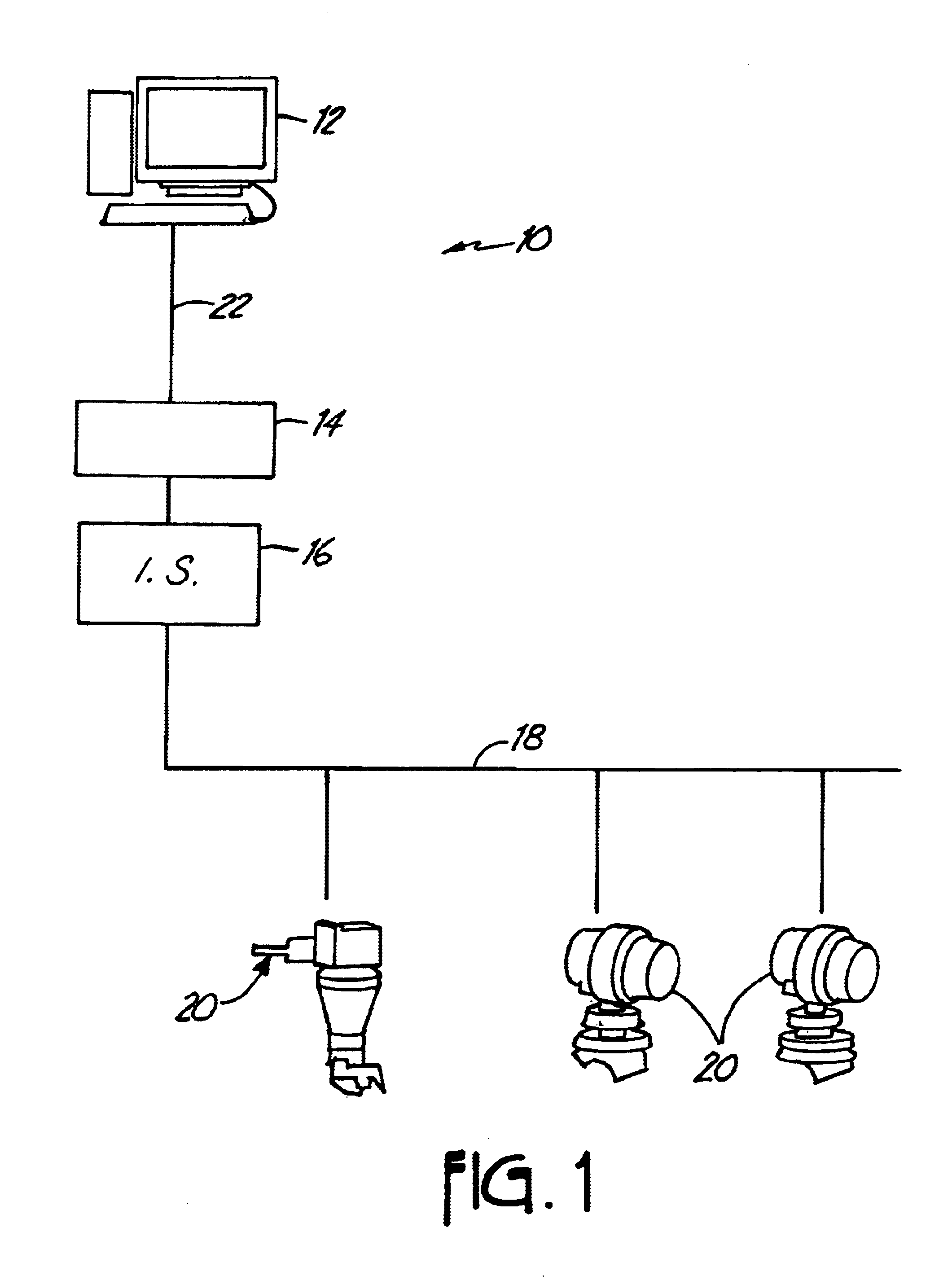
FIG. 1 illustrates an exemplary system in which embodiments of the present invention are useful. System 10 includes controller 12, I / O and control sub-system 14, intrinsic safety (IS) barrier 16, process communication loop 18 and field devices 20. Controller 12 is coupled to I / O and control sub-system 14 via link 22 which can be any suitable link such as a local area network (LAN) operating in accordance with Ethernet signaling protocols or any other suitable protocol. I / O and control sub-system 14 is coupled to intrinsic safety barrier 16 which in turn is coupled to process communication loop 18 to allow data communication between loop 18 and I / O and control sub-system 14 in a manner that limits energy passing therethrough.

Process communication loop 18 is a fieldbus process communication loop and is coupled to field devices 20, which are shown coupled to process communication loop 18 in a multi-drop configuration. The illustrated multi-drop wiring configuration vastly simplifies sy...


PUM


Abstract

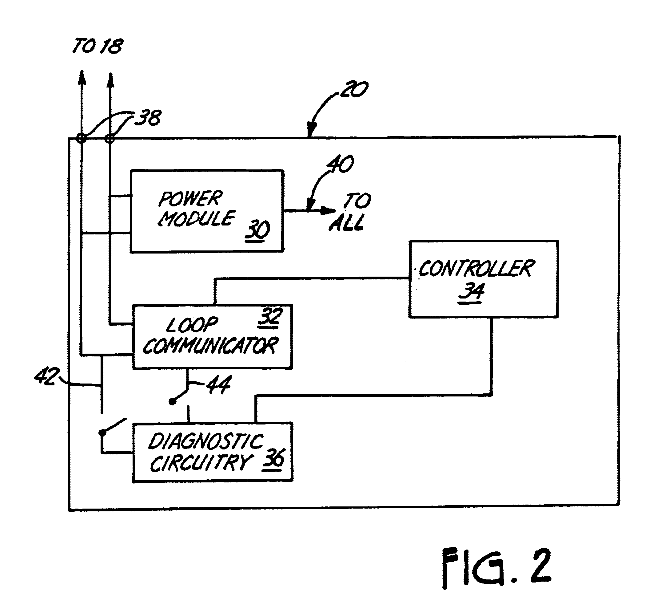
A field device includes diagnostic circuitry adapted to measure a characteristic related to a process control and measurement system. The measured characteristic is used to provide a diagnostic output indicative of a condition of the process control and measurement system. The measured characteristic can be provided to a diagnostic module that operates upon the measured characteristic to predict, or otherwise model, a condition of the process control and measurement system.

Description

BACKGROUND OF THE INVENTIONThe present invention relates to field devices operating in the process control and measurement industry. In particular, the present invention relates to field devices with improved diagnostic capabilities.Field devices, such as process variable transmitters, are used by a number of industries to remotely sense a process variable. A controller may then transmit control information to another field device, such as a valve, in the process to modify a control parameter. For example, information related to pressure of a process fluid may be transmitted to a control room and used to control a valve in an oil refining process. Other examples of a field devices include handheld configuration and / or calibration devices.One of the relatively recent advances in process control and measurement has been the implementation of all-digital process communication protocols. One example of such an all-digital communication protocol is FOUNDATION Fieldbus. Fieldbus is direct...

Claims


Application Information

Patent Timeline
Patent Type & Authority Patents(United States)
IPC IPC(8): G05B23/02
CPCG05B23/0213H04L43/18H04L12/40006G05B2219/31129H04L2012/4026G05B23/02
Inventor ERYUREK, EVRENBORGESON, DALE W.PELUSO, MARCOSROME, GREGORY H.ROPER, WESTON R.
Owner ROSEMOUNT INC
Learn More