
Blind spot warning system for an automotive vehicle

a blind spot and warning system technology, applied in the field of collision warning systems, can solve the problems of not image-based, subject to false sensing, increase reaction time, etc., and achieve the effect of decreasing the probability of collision and increasing reaction tim

Inactive Publication Date: 2005-02-22
FORD GLOBAL TECH LLC
View PDF11 Cites 352 Cited by
  • Summary
  • Abstract
  • Description
  • Claims
  • Application Information

AI Technical Summary

Benefits of technology

The present invention is an improved blind spot warning system for automotive vehicles. It uses a camera to capture images and a controller to analyze them and determine the size and position of an approaching vehicle. When a vehicle enters a blind spot, the controller activates an indicator to alert the operator of the vehicle. This system increases the reaction time of both operators and reduces the likelihood of collisions between vehicles.

Problems solved by technology

However, such systems typically are not image-based and thus are subject to false sensing.
The improved system may increase reaction time and decrease the probability of a collision occurring.

Method used


Image

  • Blind spot warning system for an automotive vehicle
  • Blind spot warning system for an automotive vehicle
  • Blind spot warning system for an automotive vehicle

Examples


Embodiment Construction

In the following figures the same reference numerals will be used to illustrate the same components. While the present invention is described with respect to a particular method and apparatus for blind spot warning, various adaptations may be evident to those skilled in the art.

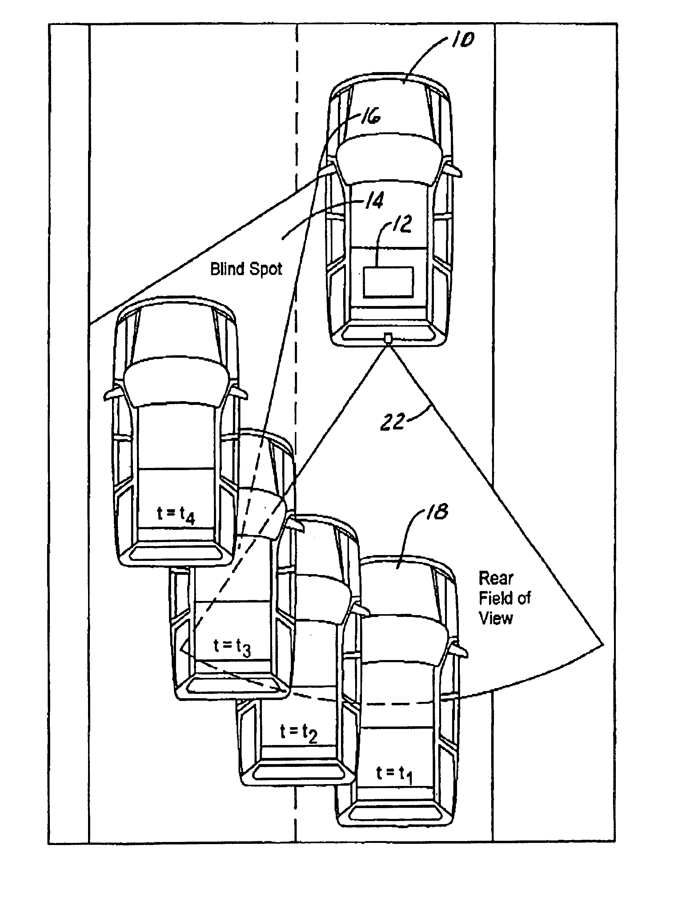
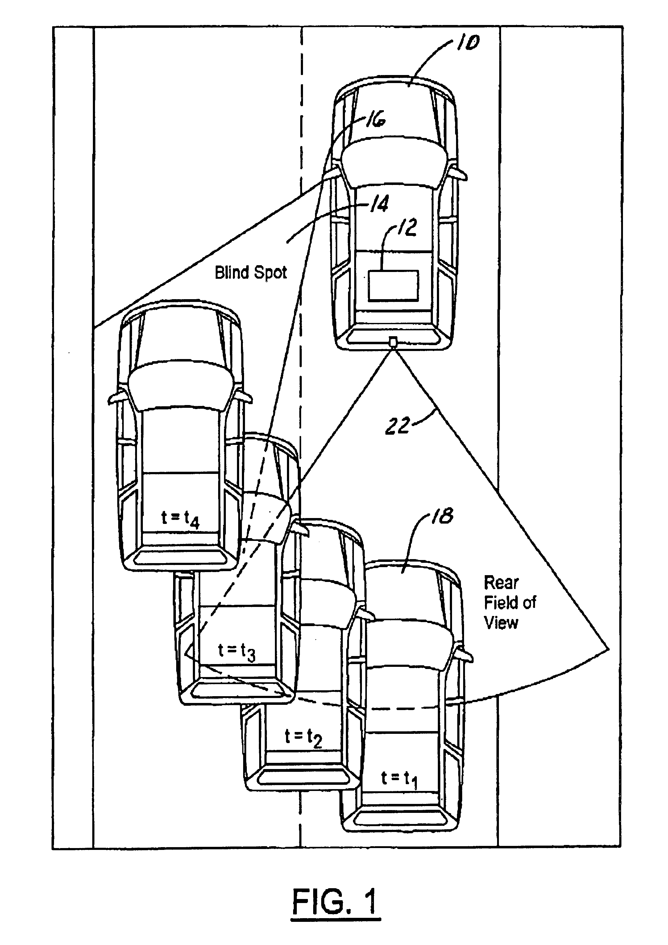
Referring now to FIG. 1, a source vehicle 10 having a blind spot warning system 12 is illustrated. A representation of a blind spot 14 is illustrated. The blind spot 14 is the area beyond which the external driver side rear-view mirror 16 cannot see without glancing back. The blind spot 14 may be of many shapes and sizes depending on various factors such as mirror size and vehicle configuration. The blind spot warning system 12 provides an indication to the source vehicle operator as to the entering of a target vehicle 18 within blind spot 14.

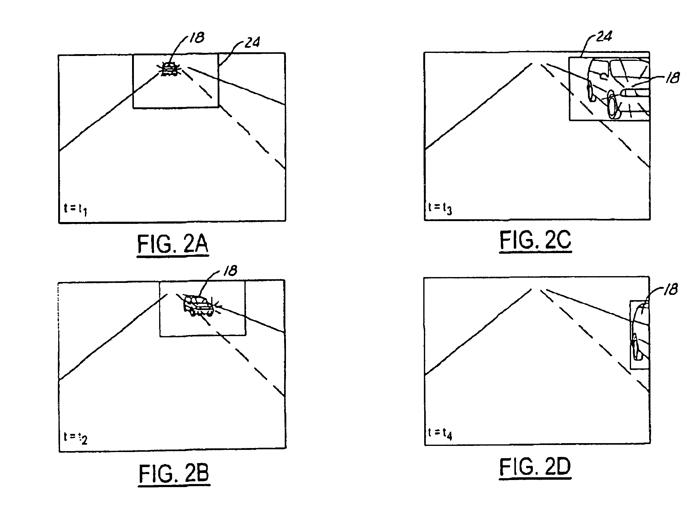
Source vehicle 10 has a rear-facing camera 20 having a field of view 22. The field of view may not overlap or slightly overlap blind spot 14. Therefore, the present inve...


PUM


Abstract

A warning system (12) for a source vehicle (10) is illustrated. A camera (20) generates a plurality of images. A controller (30) is coupled to an indicator (36). The controller (30) generates a size signal and position signal for a rear-approaching vehicle. The controller (30) activates an indicator when a rear-approaching vehicle enters a blind spot (14) in response to the size signal and position signal.

Description

BACKGROUND OF INVENTIONThe present invention relates generally to collision warning systems, and more particularly to a method and apparatus for warning a vehicle operator of another vehicle within a blind spot of the vehicle.Collision warning systems are becoming more widely used. Collision warning systems provide a vehicle operator knowledge and awareness of objects or vehicles within a close proximity so as to prevent colliding with those objects. Current collision warning systems are unitary in nature in that they only warn the operator of the vehicle containing the collision warning system of a potential collision. A sensor located on a vehicle, upon sensing an object generates an object detection signal, which is communicated to the operator of that vehicle.Warning systems for vehicles that are directed to the rear of the vehicle are known. However, such systems typically are not image-based and thus are subject to false sensing. Other rear-sensing systems monitor the rear of ...

Claims


Application Information

Patent Timeline
Patent Type & Authority Patents(United States)
IPC IPC(8): B60Q1/50B60Q1/52B60R1/00
CPCB60R1/00B60Q9/008
Inventor MILLER, RONALD HUGHTASCILLO, ANYA LYNN
Owner FORD GLOBAL TECH LLC
Learn More