
Contactless optical probe for use in semiconductor processing metrology

a technology of contactless optical probes and semiconductor processing, applied in the direction of electronic circuit testing, measurement devices, instruments, etc., can solve the problems of limited energy resolution and becoming increasingly difficul

Inactive Publication Date: 2005-02-15
VANDERBILT UNIV
View PDF11 Cites 35 Cited by
  • Summary
  • Abstract
  • Description
  • Claims
  • Application Information

AI Technical Summary

Problems solved by technology

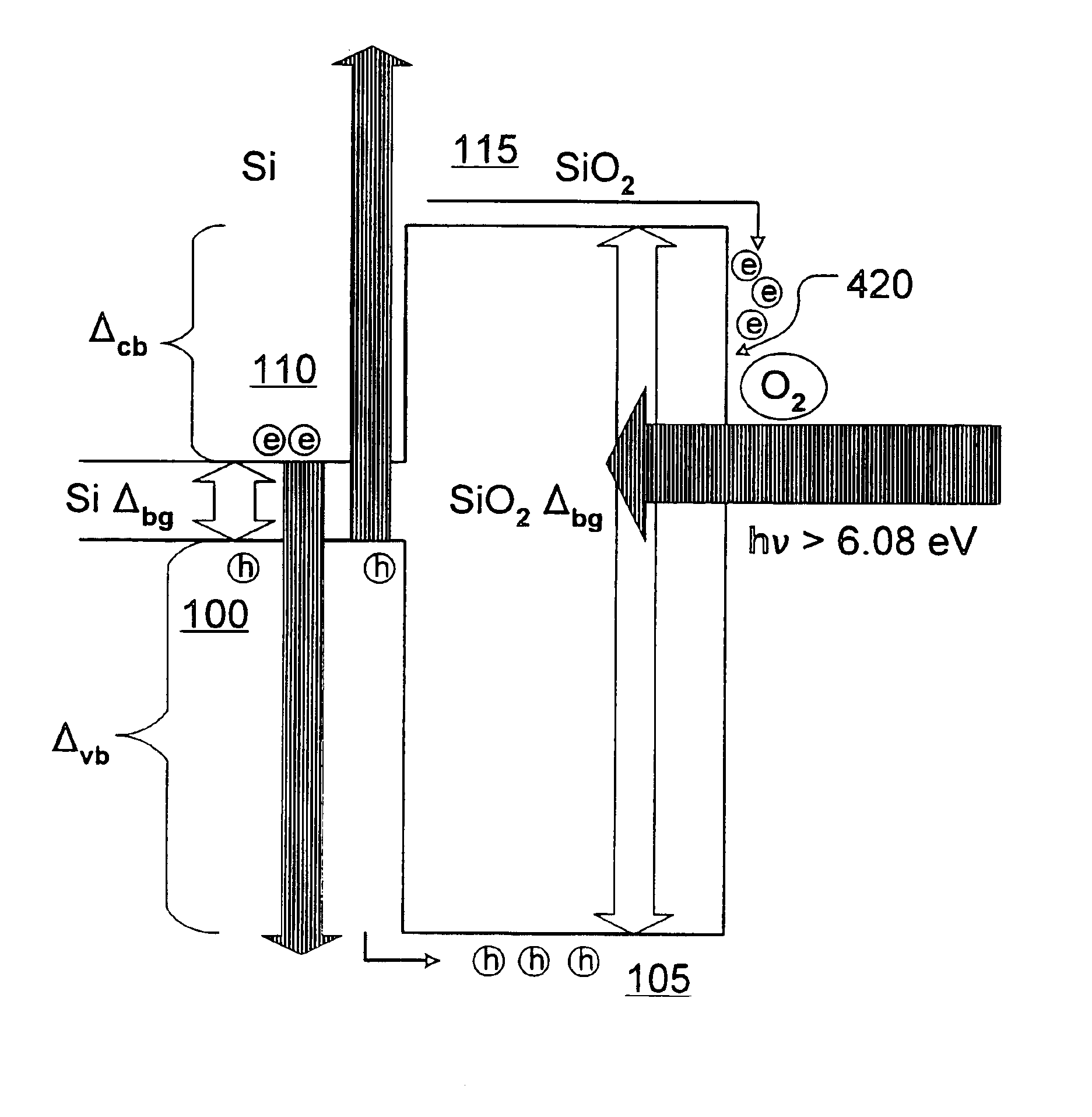
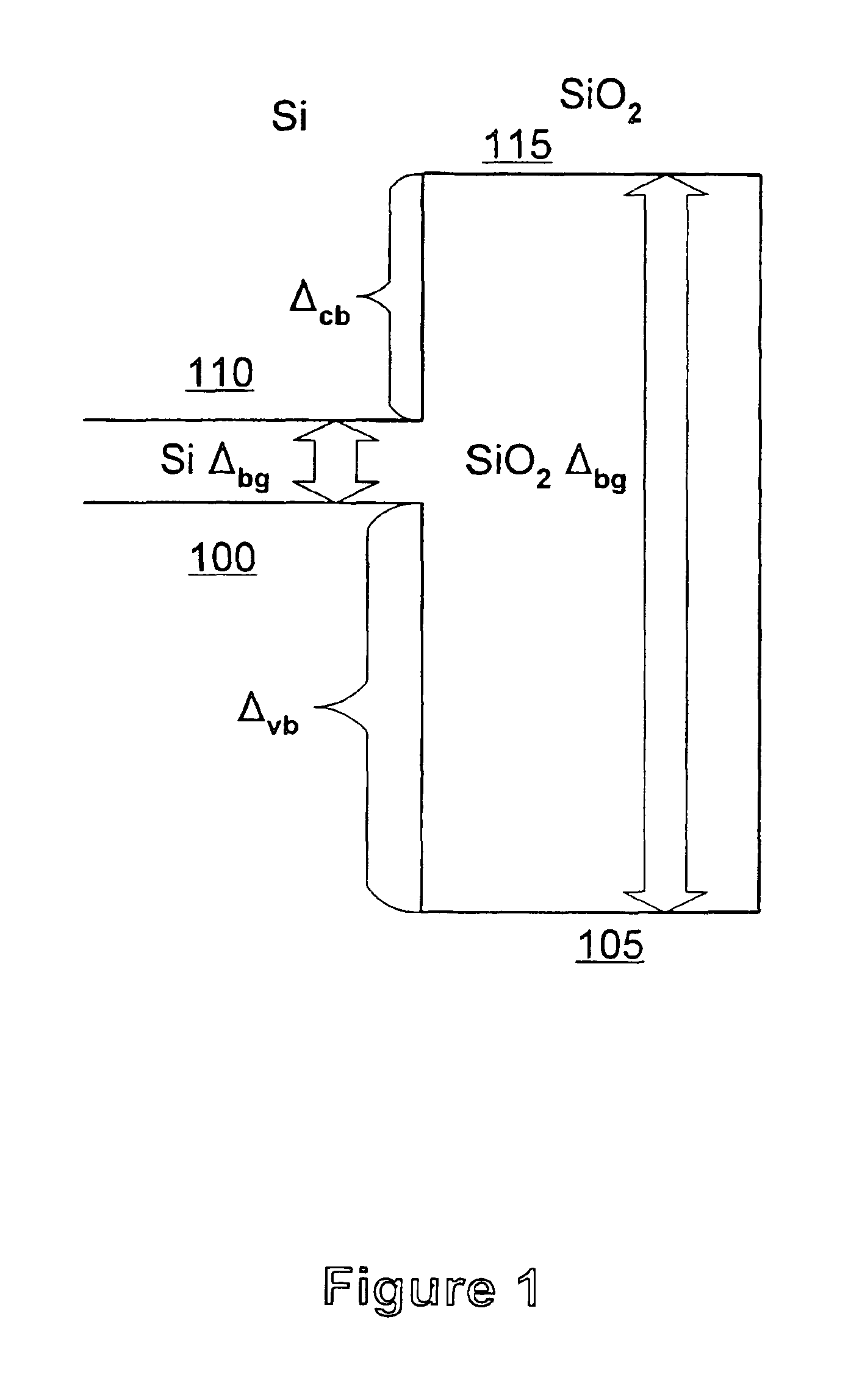
Although this technique allows contactless Δvb measurements, it utilizes X-ray photons of several tens of eVs and is therefore limited in energy resolution to a few hundred meV (a few percent of the X-ray photon energy).
This becomes increasingly difficult, as gate oxide thicknesses shrink below 40 Å. In addition, for using internal photoemission, the semiconductor has to be doped p-type or n-type to measure Δvb or Δcb, respectively.

Method used


Image

  • Contactless optical probe for use in semiconductor processing metrology
  • Contactless optical probe for use in semiconductor processing metrology
  • Contactless optical probe for use in semiconductor processing metrology

Examples


Embodiment Construction

[0024]Illustrative embodiments of the invention are described below. In the interest of clarity, not all features of an actual implementation are described in this specification. It will of course be appreciated that in the development of any such actual embodiment, numerous implementation-specific decisions must be made to achieve the developers' specific goals, such as compliance with system-related and business-related constraints, which will vary from one implementation to another. Moreover, it will be appreciated that such a development effort might be complex and time-consuming, but would nevertheless be a routine undertaking for those of ordinary skill in the art having the benefit of this disclosure.

[0025]The present invention permits band-offset measurements at semiconductor / dielectric, semiconductor / semiconductor, metal / semiconductor, and metal / dielectric heterointerfaces. As will be understood, any metal, dielectric and semiconductor, amorphous, monocrystalline or polycry...


PUM


Abstract

A method and / or device (285) for determining first and second band offsets (100, 110) at a semiconductor / dielectric heterointerface (115), which includes the semiconductor / dielectric heterointerface (115) exposed to incident photons (205) from a light source (200); a detector (275, 280) for generating a signal by detecting emitted photons (260, 265) from the semiconductor / dielectric heterointerface (115); and an element (310) for changing the energy of incident photons (205) to monitor the first and second band offsets (100, 110).

Description

[0002]The present application claims priority to provisional application Ser. No. 60 / 125,002, filed Mar. 18, 1999, the entire text and figures of which is incorporated herein by reference without disclaimer.[0003]The present invention was made with United States government support under Grants No. N00014-94-1-1023, N00014-94-1-0995, and N00014-96-1-1286 awarded by the Office of Naval Research. The United States government has certain rights in the present invention.BACKGROUND OF THE INVENTION[0004]1. Field of the Invention[0005]This invention relates generally to semiconductor processing technology, and, more particularly, to a device and method for contactless metrology.[0006]2. Description of the Related Art[0007]The physical characteristics, and, in particular, the electronic characteristics of the silicon / silicon dioxide (Si / SiO2) interface have played a major role in establishing the dominance of Si in semiconductor technology. As the physical dimensions and critical dimensions...

Claims


Application Information

Patent Timeline
IPC IPC(8): G01R31/02G01R31/311
CPCG01R31/311
Inventor TOLK, NORMAN H.LEUPKE, GUNTERWANG, WEI
Owner VANDERBILT UNIV
Learn More