Compensating shaft assembly for piston engines
- Summary
- Abstract
- Description
- Claims
- Application Information
AI Technical Summary
Benefits of technology
Problems solved by technology
Method used
Image

Examples
Embodiment Construction
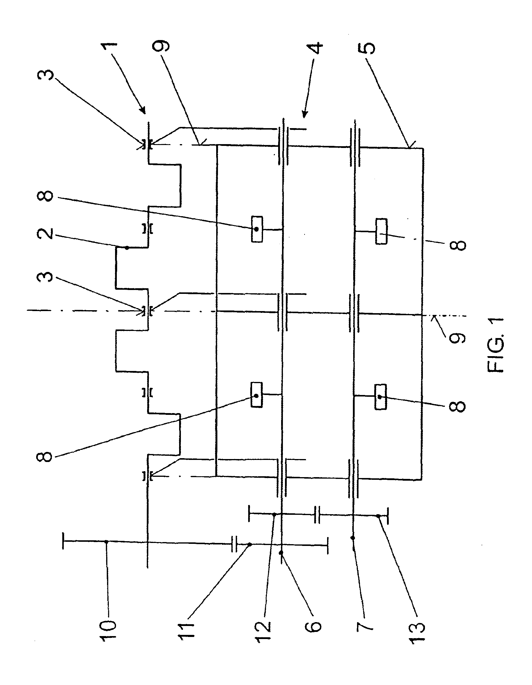
In FIG. 1, the reciprocating machine 1 is symbolized only by its crankshaft 2 and its main bearings 3. The main bearings 3 represent the complete engine block, which can be produced both in tunnel design and also with free bearing brackets. The mass balance appliance fastened to the engine block below the crankshaft 2 is generally designated by 4. It consists of a balance casing 5 and two balance shafts 6, 7, with counterweights 8, counter-rotating within the balance casing 5. The normal planes 9 through the main bearings 3 are indicated by dashed lines; the bearings of the mass balance appliance 4 are also located in these normal planes. The balance shafts 6, 7 are driven, via a drive gearwheel 11, by a gearwheel 10 torsionally connected to the crankshaft 2; the synchronizing wheels 12, 13 ensure equal counter-rotating rotational speed.
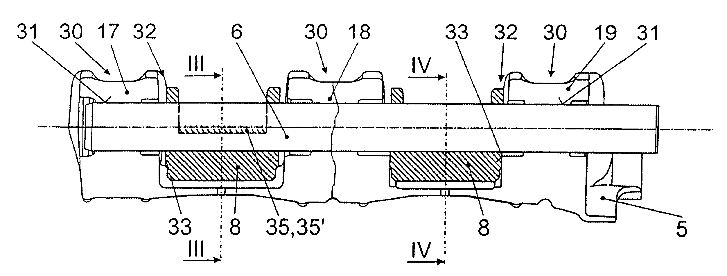
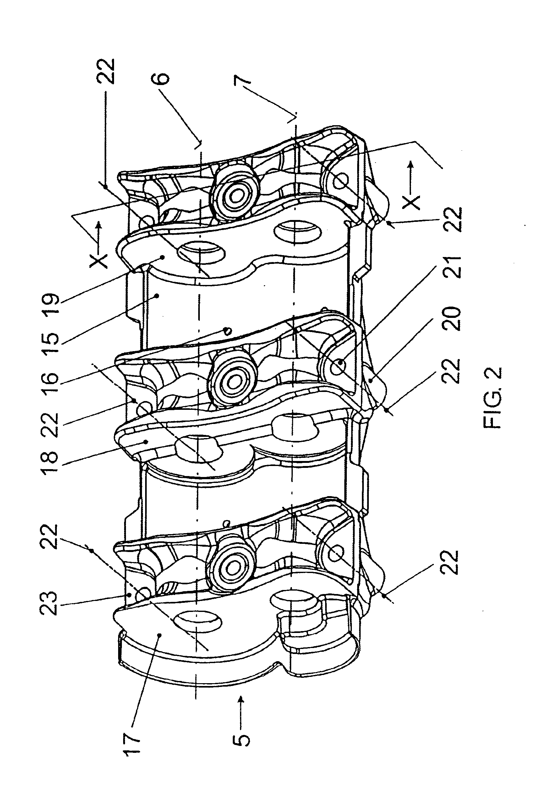
FIG. 2 shows the balance casing 5 which, in the embodiment example represented, is a part cast in light metal. It consists of a bottom shell 15 with...
PUM
 Abstract
Description
Claims
Application Information
 - R&D
- Intellectual Property
- Life Sciences
- Materials
- Tech Scout
- Unparalleled Data Quality
- Higher Quality Content
- 60% Fewer Hallucinations
Browse by: Latest US Patents, China's latest patents, Technical Efficacy Thesaurus, Application Domain, Technology Topic, Popular Technical Reports.
© 2025 PatSnap. All rights reserved.Legal|Privacy policy|Modern Slavery Act Transparency Statement|Sitemap|About US| Contact US: help@patsnap.com