Method and apparatus for measuring a frequency of an optical signal

a technology of optical signal and frequency, applied in the field of optical communication system, can solve the problems of limited spectrum utilized for transmission signal to a small fraction of occupied bandwidth, large error in absolute frequency allocation, and fundamental limitations in the increase of spectral efficiency

Inactive Publication Date: 2005-02-08
FIBERSPACE
View PDF1 Cites 17 Cited by
  • Summary
  • Abstract
  • Description
  • Claims
  • Application Information

AI Technical Summary

Benefits of technology

A method and apparatus are provided for establishing the absolute frequency of each optical carrier within a communications bandwidth having a plurality of optical carriers separated by a predetermined frequency spacing. The method includes the steps of locking the free spectral range of a plurality of optical resonators to a common microwave frequency and a means of locking each of the plurality of optical carrier frequencies to a particular mode of an optical resonator. The method further includes locking the free spectral range of an offset resonator to a known mic

Problems solved by technology

The prior use of wavelength division multiplexing techniques in fiber optic networks has generally limited the spectrum utilized for the transmission signal to a small fraction of the occupied bandwidth.
This is because in general any given component technology operates over a limited bandwidth.
A large spectral separation between neighboring optical channels in a WDM system allows for a great deal of error in absolute frequency allocation.
Furthermore, increases in spectral efficiency are fundamentally limited when the Fourier bandwidth of the signal exceeds the flat portion of the filter passband width.
As these limits are reached, transmission impairments caused by frequency errors result.
Alternatively, the laser itself may fail.
If the optical carrier frequency changes by too much (or if the laser fails), downstream detecting and decoding can no longer function properly in a WDM system.
The ultra-high frequency of individual optical carriers makes such frequency measurement difficult.

Method used


Image

  • Method and apparatus for measuring a frequency of an optical signal
  • Method and apparatus for measuring a frequency of an optical signal
  • Method and apparatus for measuring a frequency of an optical signal

Examples


Embodiment Construction

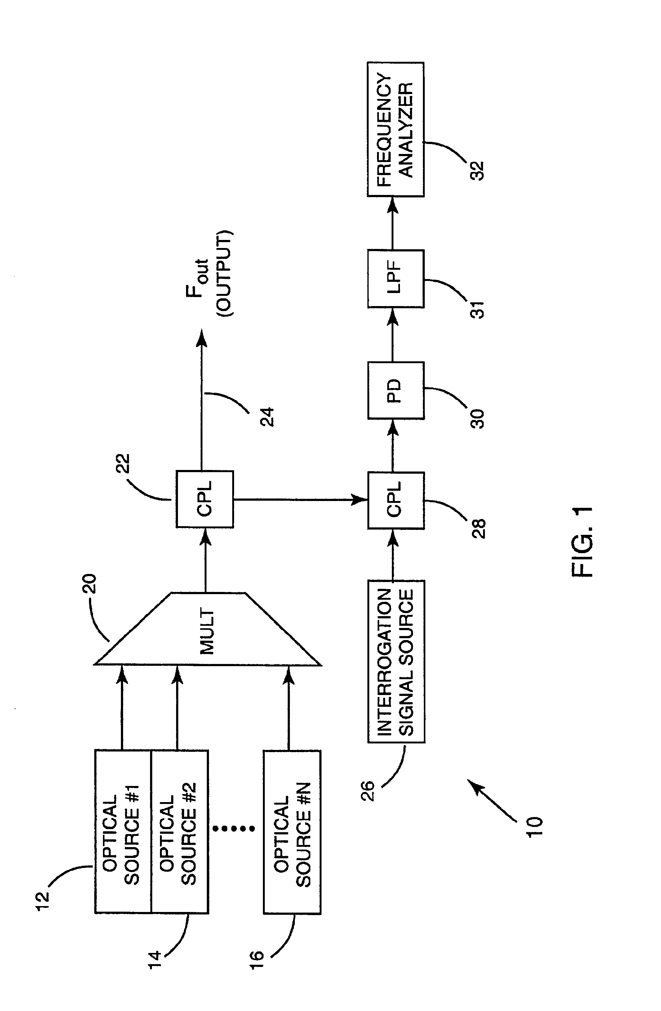
FIG. 1 depicts a system 10 for measuring and stabilizing the frequency of each individual optical carrier component contained in an output signal Fout comprising a plurality of optical carrier frequencies. In such an embodiment, the optical carrier frequencies may be locked to adjacent modes of a reference resonator (or to multiple reference resonators that are maintained at a common free spectral range). As shown, signals from a number of optical sources 12, 14, 16 may be combined in a multiplexing filter 20 and transferred to a user (not shown) at a remote location through an optical waveguide 24 (e.g., an optical fiber).

The optical signal generation system 10 may be one-way or two-way communications system that carries information (e.g., telephone, Internet, Intranet, Ethernet, CATV, etc.) using a number of optical carriers. The sources 12, 14, 16 may be continuous wave reference frequencies or they may be modulated in the optical communications system application. Further, the f...


PUM


Abstract

A method and apparatus are provided for detecting a frequency of an optical signal within a communications channel having a plurality of optical carriers separated by a predetermined frequency spacing. The method includes the steps of locking an optical carrier frequency to an axial mode of an optical resonator of known free spectral range; providing an additional optical resonator as a reference having a known free spectral range that differs from that of the first optical resonator; locking an optical reference signal to a closest axial mode of a reference optical resonator producing an optical reference signal that is spectrally offset from said optical carrier frequency by a spectral quantity less than the known free spectral range; mixing the optical carrier frequency with the reference optical signal frequency thus generating a difference signal as a beat frequency; and measuring a frequency of a difference signal.

Description

FIELD OF THE INVENTIONThe field of the invention relates to communication systems and more particularly to optical communication systems.BACKGROUND OF THE INVENTIONMethods of transmitting and receiving communications signals over fiber optic networks are known. Wavelength division multiplexing (WDM) techniques are also known in the context of optical communications systems. Such techniques have been applied to a variety of communications networks, including metropolitan local area networks, regional wide area networks and long distance communications networks. In fact wavelength division multiplexing is a standard technique used today to increase aggregate capacity in fiber optic communications systems.The prior use of wavelength division multiplexing techniques in fiber optic networks has generally limited the spectrum utilized for the transmission signal to a small fraction of the occupied bandwidth. This approach has been effective to increase capacity by combining multiple digit...

Claims


Application Information

Patent Timeline
IPC IPC(8): G01J9/00G01J9/04
CPCG01J9/04
Inventor MELLS, BRADLEY
Owner FIBERSPACE
Why Eureka
Try Eureka