
Hole cutting tool

a cutting tool and hole technology, applied in the field of surface equipment for cutting holes, can solve the problems of defective hole cutting techniques, increasing the need of electricians in the field, and unable to meet the needs of the industry

Inactive Publication Date: 2005-02-08
PYTHON PERFECT CUTTER
View PDF18 Cites 45 Cited by
  • Summary
  • Abstract
  • Description
  • Claims
  • Application Information

AI Technical Summary

Benefits of technology

"The present invention provides an improved hole cutting tool that overcomes the limitations of prior art techniques. The tool has a unique frame assembly with multiple pneumatically isolated suction chambers that enable the frame to self-adhere to porous surfaces. The tool includes a template for cutting a hole in a surface and a source of negative air pressure to secure the frame against the surface. The tool can be easily switched between attachment chambers to cut holes in different locations. The invention also includes a support shelf for holding fixtures and a removable template for vacuuming dust particles during the cutting process. The technical effects of the invention include improved hole cutting efficiency, ease of use, and improved surface quality."

Problems solved by technology

However, prior art hole cutting techniques (with the exception of the prior art technique previously developed by one of the inventors of the present invention as disclosed and incorporated below) were defective in meeting the needs of the industry.
However, it has been determined that electricians in the field are increasingly needing to place electrical outlet boxes that are larger than the standard double gang outlet box, such as two or more double gang boxes in series in the same hole location.
Although an electrician could simply use a double gang box template to cut overlapping cuts to form a larger hole, such an application was problematic with the Tillemans '811 apparatus because the previously cut hole would undesirably interfere with the self-adhesion properties of the Tillemans '811 apparatus.
In addition, the Tillemans '811 apparatus was ineffective at adhering to a porous surface, such as a “popcorn” ceiling.

Method used


Image

  • Hole cutting tool
  • Hole cutting tool
  • Hole cutting tool

Examples


Embodiment Construction

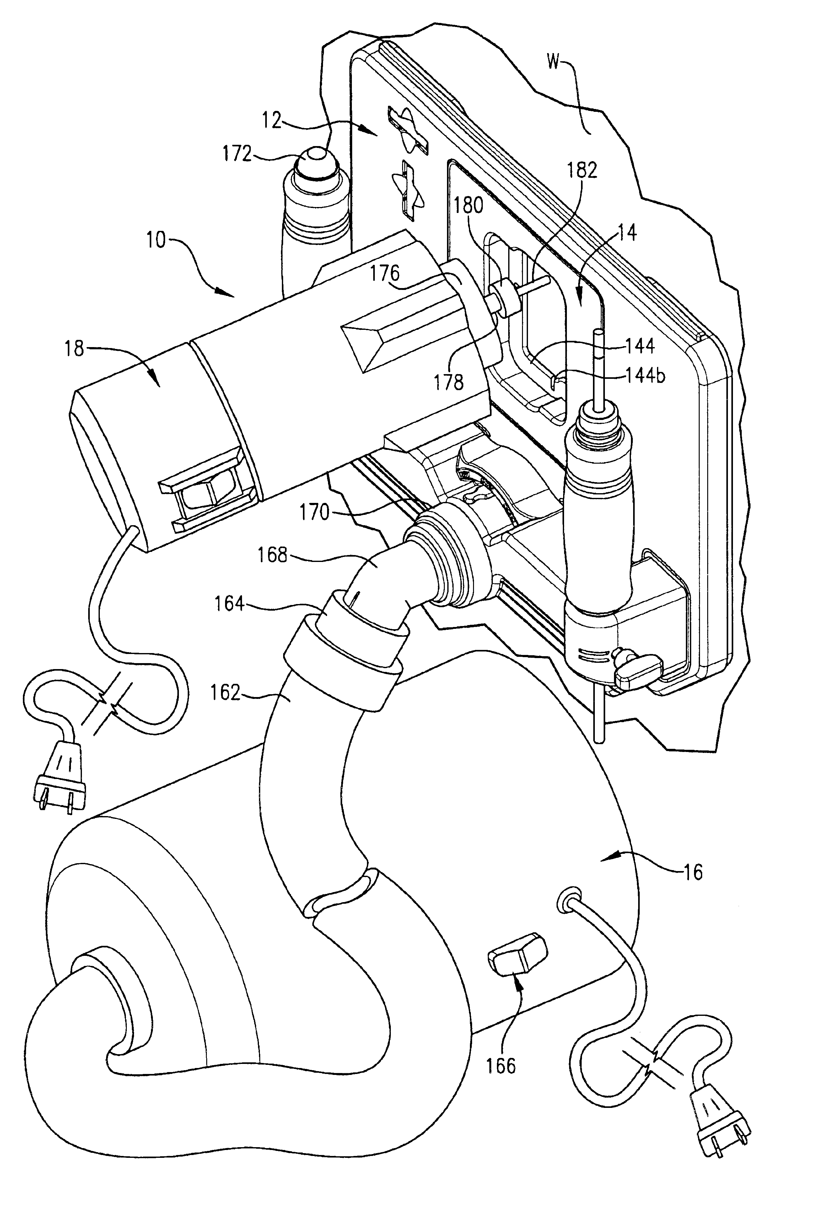
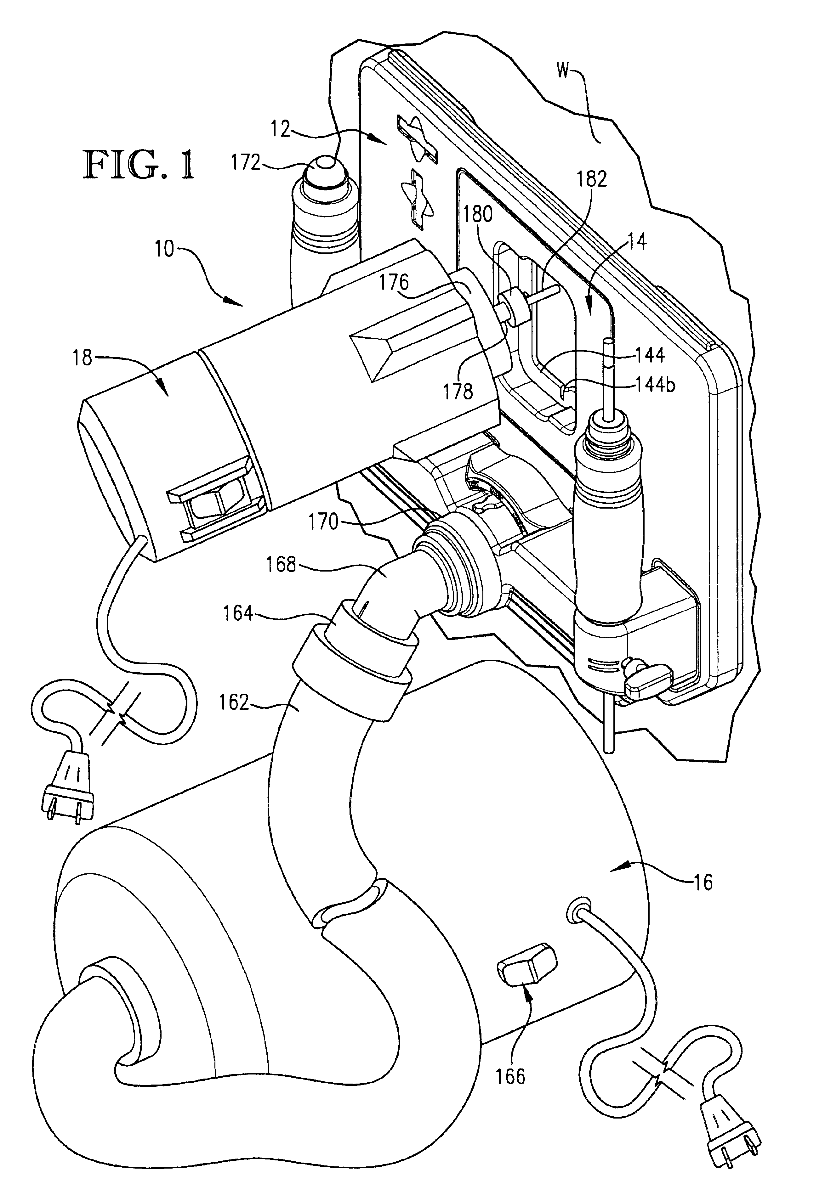
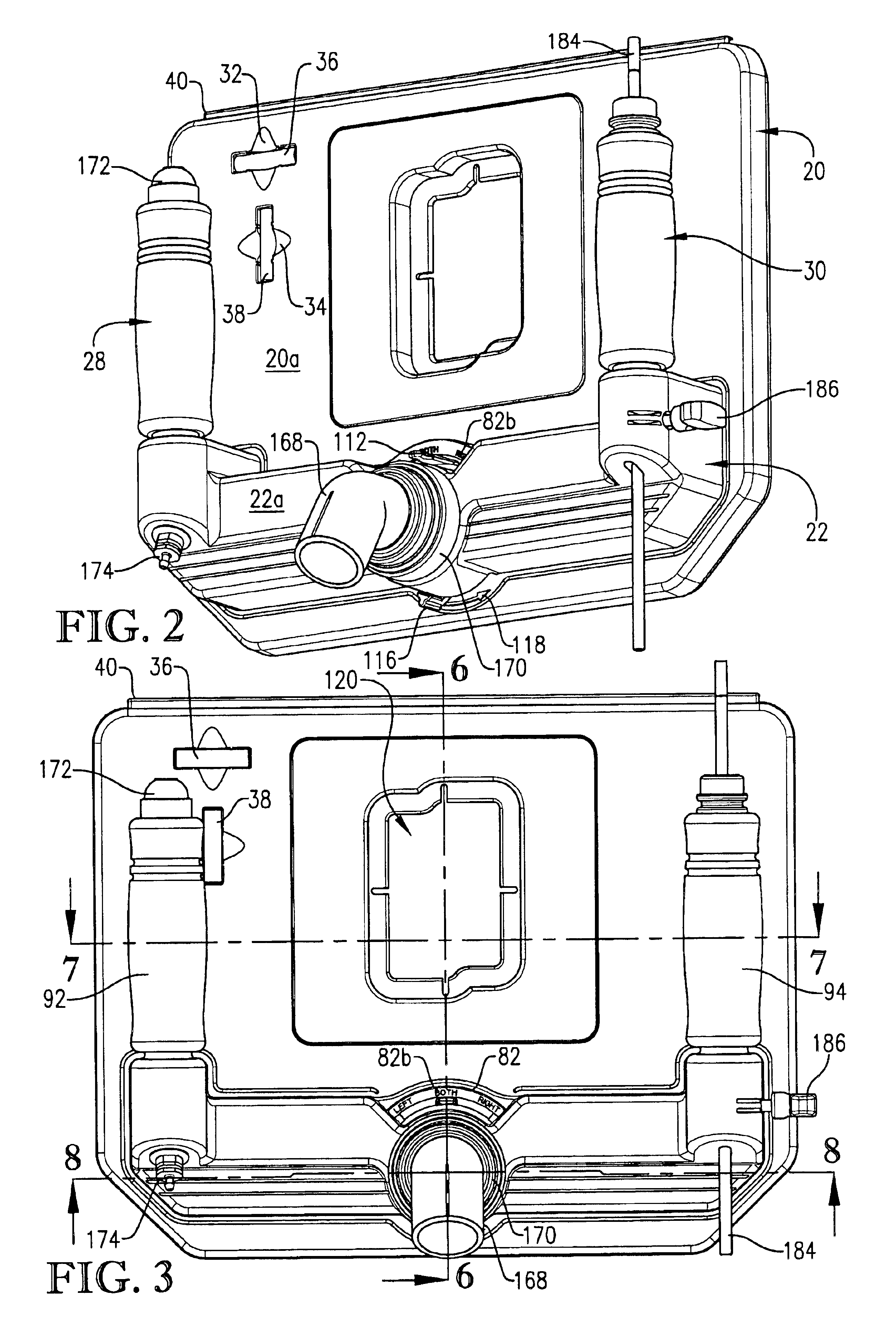
FIG. 1 illustrates a hole cutting tool 10 constructed in accordance with the principles of a preferred embodiment of the present invention and configured for cutting an accurately located and precisely shaped hole in a surface, such as a wall W of a finished residential or commercial building. Although the hole cutting tool 10 is illustrated in use on the finished wall W, the principles of the present invention are not limited to finished wall applications, or even to hole cutting applications. As further detailed below, the principles of the present invention are equally applicable to hole cutting applications on virtually any surface, including ceilings and floors, whether finished or unfinished, flat surfaces as well as semi-flat surfaces, such as textured walls, ceilings, and floors. Additionally, while the principles of the present invention are particularly well suited for hole cutting applications, the principles of the present invention are also applicable to other construct...


PUM

PropertyMeasurementUnit
air pressureaaaaaaaaaa
pressureaaaaaaaaaa
thermoplasticaaaaaaaaaa

Abstract

A hole cutting tool (10) configured for cutting an accurately located and precisely shaped hole in a surface, such as a wall (W) of a finished residential or commercial building is disclosed. The tool (10) provides a frame assembly (12) which is self-adhering to the surface (W) and carries removable templates (14, 146-152) for handsfree use in cutting an accurately located and precisely shaped hole. The unique frame assembly (12) provides multiple selectable, pneumatically isolated suction chambers (50,52) that enable the self-adhesion function even when the frame assembly (12) is placed over existing holes in the surface (W). The suction chambers (50,52) are formed in part by a unique corrugated gasket (56) that enables the frame assembly (12) to self-adhere to porous surfaces. The removable template (14) enables dust particles created during the cutting process to be simultaneously vacuumed away regardless of the orientation of the template (14) relative to the frame assembly (12).

Description

BACKGROUND OF INVENTION1. Field of the InventionThe present invention relates generally to equipment for cutting holes in surfaces, such as walls or ceilings, for receiving construction components, such as electrical outlet boxes, recessed light fixtures, and the like. More specifically, the present invention concerns a hole cutting tool that provides a frame assembly which is self-adhering to the surface and carries a removable template for use in cutting an accurately located and precisely shaped hole. The unique frame assembly provides multiple selectable, pneumatically isolated suction chambers that enable the self-adhesion function even when the frame assembly is placed over existing holes in the surface. The versatile self-adhesion function enables the inventive frame assembly to be used to cut a wide variety of desirably shaped holes using one or more templates in a handsfree manner. In a preferred embodiment, the suction chambers are formed in part by a unique gasket that en...

Claims


Application Information

Patent Timeline
Patent Type & Authority Patents(United States)
IPC IPC(8): B23D47/00B23D5/00B23D9/00B23D5/04B23D1/30B23C1/00B23D3/00B23D3/06B23D1/00B23D39/00B23C1/20B27C5/00B27C5/10B23Q9/00B23Q11/00B25H1/00B25H3/06B26D
CPCB23Q9/0014B23Q11/0046B25H1/0064B25H3/06Y10T409/306608Y10T409/303752Y10T409/30644Y10T408/554Y10T409/304088Y10T408/50Y10T409/303696Y10T409/303808Y02P70/10
Inventor TILLEMANS, GREGORY M.STARKEY, JAMES L.
Owner PYTHON PERFECT CUTTER
Learn More