
Fast coupler with connection indicator

a technology of fast couplers and indicators, which is applied in the direction of hose connections, hose couplings, pipes/joints/fittings, etc., can solve the problems of mislead the fitter, device structure stems from its very structure, and high resistan

Inactive Publication Date: 2005-02-08
LEGRIS
View PDF17 Cites 17 Cited by
  • Summary
  • Abstract
  • Description
  • Claims
  • Application Information

AI Technical Summary

Benefits of technology

"The present invention proposes a new structure for a captive indicator device that does not affect the size of the coupling and can be put back after coupling to confirm that the coupling is properly implemented and maintained. The invention provides a quick coupler for a fluid circuit with a male portion and a female portion, and a connection indicator device that is snap-fastened onto the female portion. The indicator device has a ring-shaped portion surrounding the hydraulic circuit closed by the coupler, with tabs that have teeth that snap into the latch of the coupler. This new structure allows for easier and more convenient maintenance and replacement of the indicator device."

Problems solved by technology

A poorly-established connection is firstly a source of leaks and secondly a risk of uncoupling which has the consequence at very least of causing the machine including said pressurized fluid circuits to break down, and if the machine is a motor vehicles, and which can constitute the cause of an accident (no pressure in pneumatic braking circuits, fuel leaking into the engine compartment leading to a fire .
One of the drawbacks of those devices stems from their very structure.
Under such circumstances, the device presents a high degree of resistance to insertion of the male element of the coupler into the female element, and that can mislead the fitter into believing that a proper connection position has been reached.
The compromise that is used in practice is such that the key for confirming connection can be extracted from its housing merely by being manipulated, which constitutes a drawback.

Method used


Image

  • Fast coupler with connection indicator
  • Fast coupler with connection indicator

Examples


Embodiment Construction

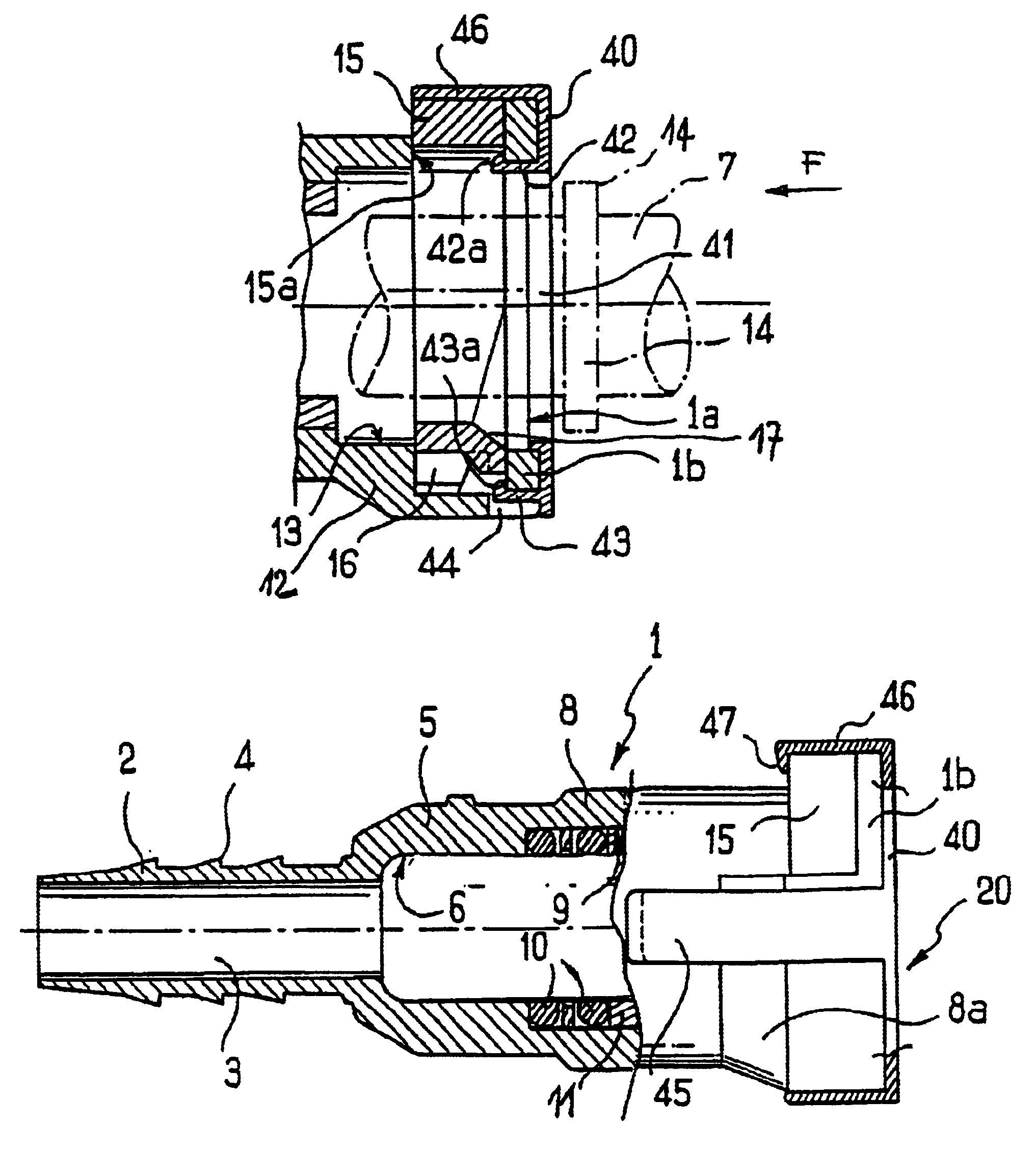
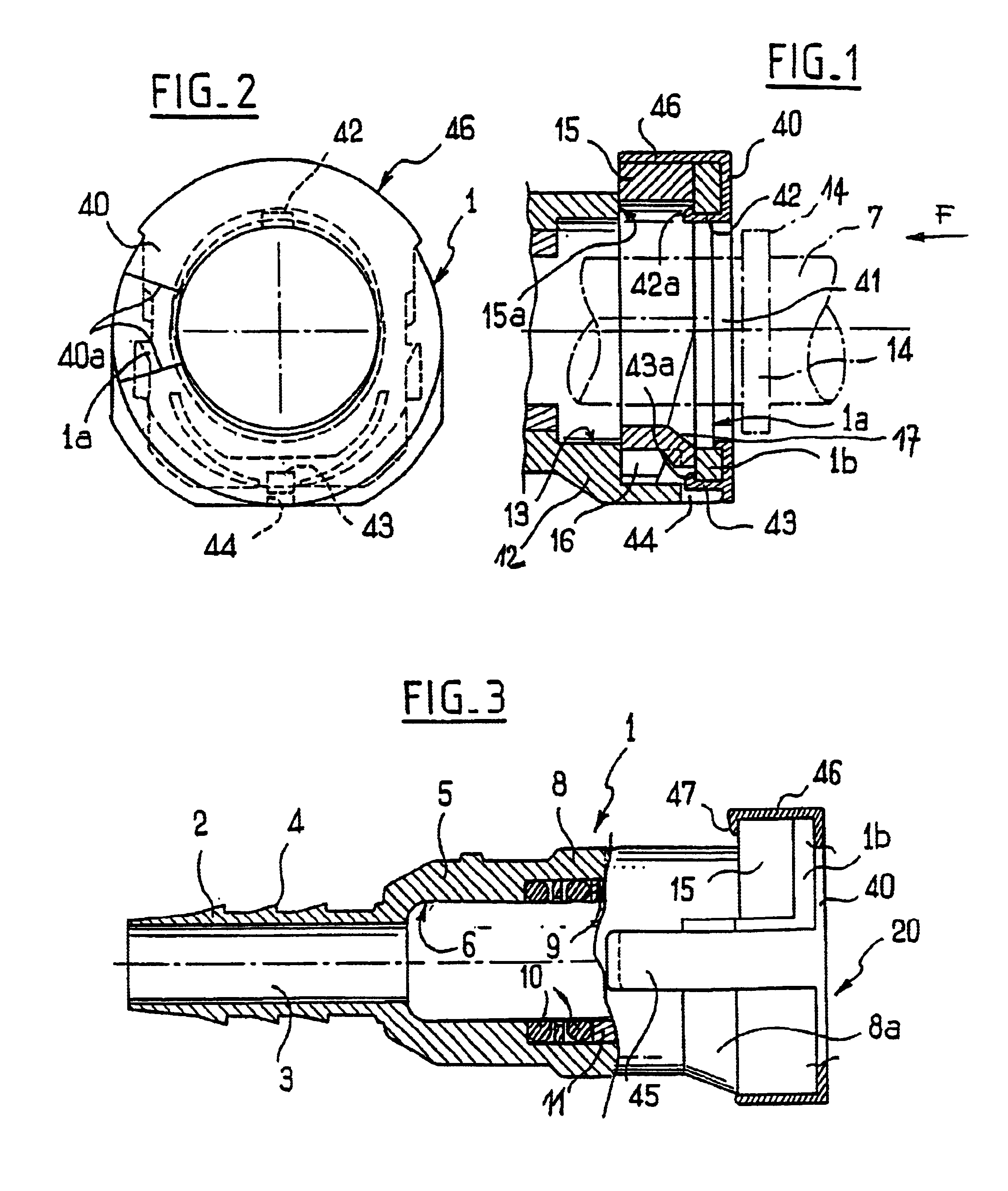
A coupler of the invention includes a female portion 1 divided into a plurality of sections. A first section 2 constitutes a spigot having an inner channel 3 and outer christmas-tree shaped barbs 4 for inserting in a hose (not shown). The second section 5 of said portion 1 has a counterbore 6 of determined diameter for receiving the tip of an endpiece 7 forming the male portion of the coupler.

The third section 8 of said female portion has a counterbore 9 of diameter greater than the counterbore 6, for receiving two O-rings 10 and an insert 11 for blocking said O-rings. The inside diameter of the insert is equal to the diameter of the counterbore 6. The inside diameter of the insert is equal to the diameter of the counterbore 6. Finally, the female portion 1 has a fourth section 12 having an inside diameter 13 that is even greater than the diameter of the above-mentioned counterbores, so as to enable a collar 14 carried by the endpiece 7 to pass freely therethrough. As its outwardly-...


PUM


Abstract

A fast coupler for a fluid connection includes a male part and a female part. The female part having a staged counterboring whereof the cross-section of larger diameter can receive an outer flange of the male part, beyond a mobile lock in a housing transverse to the counterboring. The coupler also includes a connection indicating device locked on the female part by a device partly housed in the housing and deactivated by the flange of the male part when it is inserted into the counter boring. The indicator device may include a member for permanent connection to the closed fluid circuit by the coupler.

Description

The present invention relates to a quick coupler comprising a male portion and a female portion which couple together merely by inserting one into the other, and it relates more particularly to a quick connector which possesses means enabling the quality of the coupling achieved to be verified quickly.BACKGROUND OF THE INVENTIONIn circuits conveying fluids under pressure and making use of quick couplers, it is desirable, or even required, to be guaranteed that connections are made properly. A poorly-established connection is firstly a source of leaks and secondly a risk of uncoupling which has the consequence at very least of causing the machine including said pressurized fluid circuits to break down, and if the machine is a motor vehicles, and which can constitute the cause of an accident (no pressure in pneumatic braking circuits, fuel leaking into the engine compartment leading to a fire . . . ).Numerous manufacturers have made proposals for associating quick couplers of this typ...

Claims


Application Information

Patent Timeline
Patent Type & Authority Patents(United States)
IPC IPC(8): F16L37/00F16L37/084
CPCF16L37/0841F16L2201/10
Inventor PODER, PHILIPPE
Owner LEGRIS
Learn More