Control apparatus for transmission

a technology of control apparatus and work vehicle, which is applied in the direction of interengaging clutches, hybrid vehicles, gearing, etc., can solve problems such as reducing the traveling speed of work vehicles

Inactive Publication Date: 2005-02-08
KUBOTA LTD
View PDF12 Cites 9 Cited by
  • Summary
  • Abstract
  • Description
  • Claims
  • Application Information

AI Technical Summary

Benefits of technology

A primary object of the present invention is to provide a control apparatus for a work-vehicle transmission capable of reducing a change-speed shock when the transmission clutch is operated, in response to a change-speed instruction to automatically operate the transmission clutch into the non-transmitting state to operate the gear change-speed mechanism by means of an actuator and subsequently operate the transmission clutch back to the transmitting state.
The basic mode described above is a change-speed control mode which places priority on the speediness of the change-speed operation, rather than on the prevention of change-speed shock. On the other hand, in the alternate control mode, the above-described dual-transmitting condition and the power transmission with minimized torque variation will be realized in repetition in the course of shifting from the previous speed position prior to issuance of the change-speed instruction to the target speed position instructed by the change-speed instruction. So, this is a change-speed control mode for realizing shockless shift from the previous speed position prior to issuance of the change-speed instruction to the target speed position instructed by the change-speed instruction. Further, in the skip change-speed mode, in the realization of the dual-transmitting state and the power transmission with reduced torque variation to the traveling unit, the time required for shifting from the previous speed position prior to issuance of the change-speed instruction to the target speed position instructed by the change-speed instruction is shorter, in comparison with the alternate control mode. Hence, this is a mode designed to achieve both speediness of change-speed operation and low change-speed shock at one time.

Problems solved by technology

As a result, it has become possible to restrict, during a change-speed operation, occurrence of reduction in the traveling speed of the work vehicle due to the traveling load.

Method used


Image

  • Control apparatus for transmission
  • Control apparatus for transmission
  • Control apparatus for transmission

Examples


Embodiment Construction

[1]

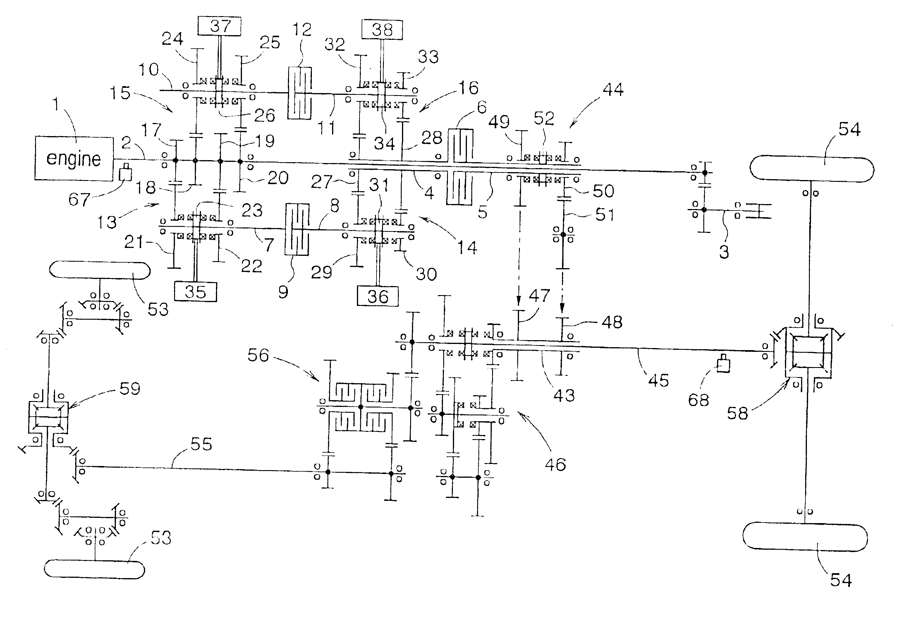
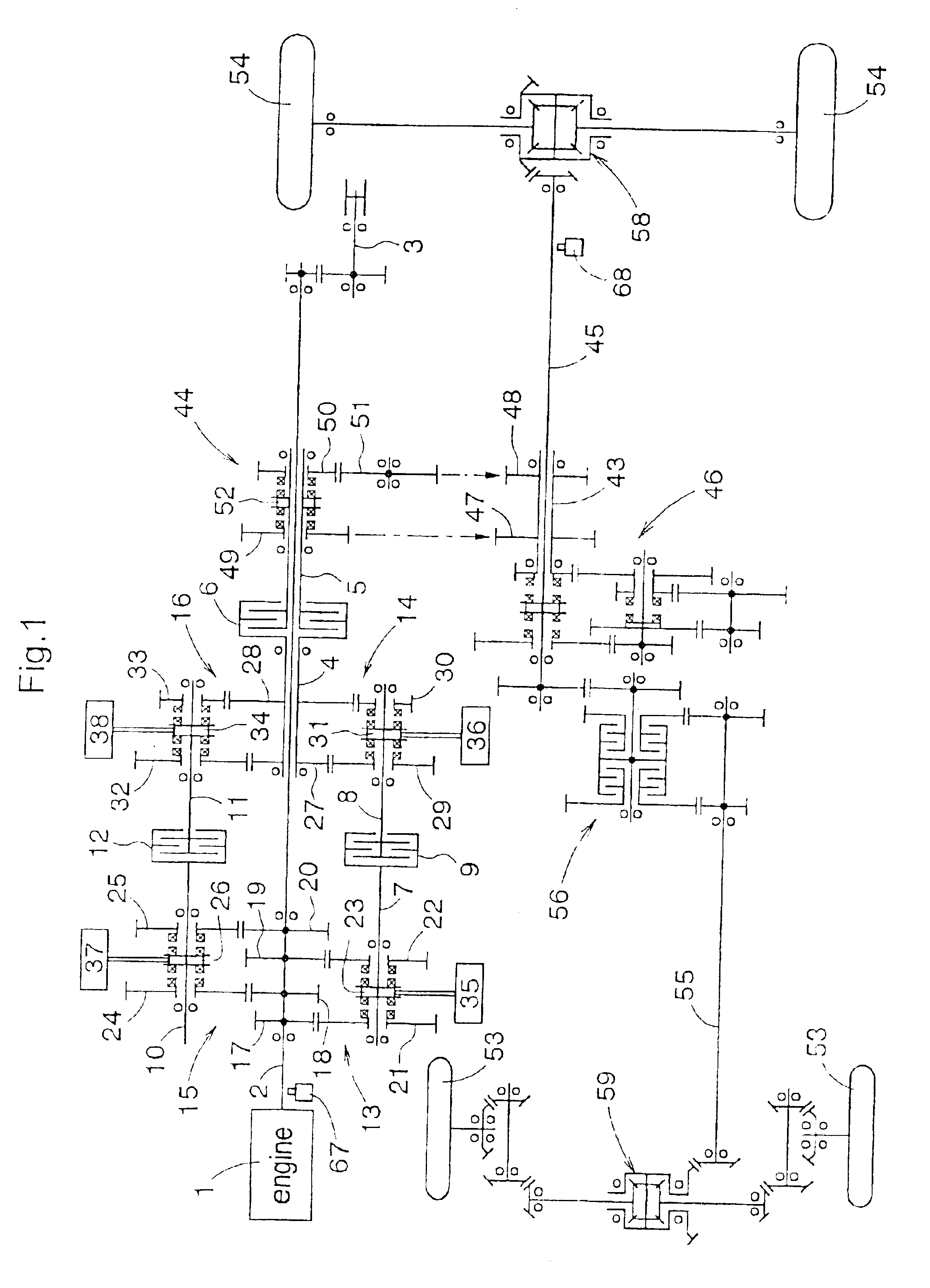
FIG. 1 shows a traveling transmission line of a four-wheel-drive agricultural tractor as an example of a work vehicle. In this, power of an engine 1 is transmitted to a transmission shaft 2 and to PTO shaft 3. On the transmission shaft 2, tubular transmission shafts 4, 5 are mounted to be rotatable relative to each other and a hydraulic multiple-disc friction type transmission clutch 6 is interposed between the transmission shafts 4, 5. In response to supply of a working fluid thereto, the transmission clutch 6 is operated to a power transmitting state. In response to discharge of the working fluid therefrom, the clutch 6 is operated to a power non-transmitting state.

As shown in FIG. 1, in parallel to the transmission shafts 2, 4, a first main transmission shaft 7 and a first auxiliary transmission shaft 8 are disposed. Between these first main and auxiliary transmission shafts 7, 8, a first friction clutch 9 is disposed. In parallel also to the transmission shafts 2, 4, a second...


PUM


Abstract

A transmission control apparatus includes transmission lines disposed between a pair of transmission shafts and a hydraulic multiple disc transmission clutch disposed on one side of the transmission lines. Power from an engine is transmitted via one of the transmission lines to a traveling unit. Each of the transmission lines has a friction clutch. A first gear mechanism operated by a first actuator is disposed between one of the transmission shafts and the first transmission line. A second gear mechanism operated by a second actuator is disposed between one of the transmission shafts and the second transmission line. When the first transmission line is powered, a first system operates the second gear mechanism into a speed position; the first clutch to a non-transmitting state and the second clutch to a transmitting state, thereby providing a progressive shifting of the transmission clutch from a transmitting state to a semi-transmitting state.

Description

BACKGROUND OF THE INVENTION1. Field of the InventionThe present invention relates to a control apparatus for a work-vehicle transmission having a transmission clutch and a gear change-speed mechanism. This control apparatus is operable, in response to an instruction for change speed, to automatically operate the transmission clutch into a non-transmitting state to operate the gear change-speed mechanism by means of an actuator and subsequently to automatically operate the transmission clutch back to a transmitting state.2. Description of the Related ArtAn example of the work-vehicle transmission to be controlled by the above-described control apparatus is disclosed by Japanese Patent Application “Kokai” No.: Hei. 6-313478. In this, a gear change-speed mechanism (denoted with a mark A in FIG. 1) to be operated by actuators (denoted with marks T1, T2 in FIG. 1) and a hydraulic multiple disc clutch (denoted with numeral 19 in FIG. 1) are arranged in series. With this, in response to a ...

Claims


Application Information

Patent Timeline
IPC IPC(8): F16H61/04F16H61/70F16H59/52F16H61/688F16H59/50F16H59/48F16H61/68B60W10/02B60W10/12B60W30/18F16H61/08
CPCB60W10/14B60W30/18F16H61/0437B60W10/02B60K2741/225Y10T477/689B60Y2200/221B60Y2200/41F16H59/48F16H59/52F16H61/688F16H61/70F16H63/46F16H2061/0444F16H2306/14F16H2306/44F16H2306/52F16H2342/04F16H2059/147Y10S477/904Y10S477/90F16H2059/425Y10T477/65Y10T74/19247Y10T74/1926Y10T74/19251Y10T477/69335B60W10/10B60W30/1819B60W20/00
Inventor UMEMOTO, SUSUMUYAMAGUCHI, TETSUOHANA, HIDETOSHIKAWAI, ISAMUYASUMI, TAKASHIHORIUCHI, YOSHIFUMIFUKUI, TETSU
Owner KUBOTA LTD
Why Eureka
Try Eureka