Voice coil motors and magnetic circuits therefor

a voice coil motor and magnetic circuit technology, applied in the direction of magnetic circuit shape/form/construction, instruments, record information storage, etc., can solve the problems of difficult to secure the magnet to the yoke at the registered position, high cost and less production, etc., to achieve more accurate positioning of the magnetic head, reduce torque variation, and high production efficiency

Inactive Publication Date: 2012-05-10
YAMADA HIROYUKI +2
View PDF7 Cites 3 Cited by
  • Summary
  • Abstract
  • Description
  • Claims
  • Application Information

AI Technical Summary

Benefits of technology

[0007]An object of the invention is to provide a magnetic circuit for a voice coil motor having the advantages of more accurate positioning of a magnetic head, minimized torque variation, and highly effective magnet production; and a voice coil motor.
[0008]It has been found that when the magnet used in a voice coil motor is formed to a rectangular prism or parallelepiped prism shape, there are achieved advantages of minimized torque variation and more accurate positioning of a magnetic head. The invention is predicated on this finding.
[0020]Combination of a magnet of rectangular prism or parallelepiped prism shape with a yoke and a coil of proper shape provides a magnetic circuit which facilitates positioning and holding of the coil. The voice coil motor is more accurate in positioning the magnetic head.

Problems solved by technology

To form a magnet of an arcuate or similar shape, a mold of a corresponding shape must be prepared and worked such as by shaping, cutting, grinding or otherwise machining, which operation is expensive and less productive.
In the event a magnet of an arcuate or similar shape is used, it is difficult to secure the magnet to the yoke at the registered position.
A problem arises particularly in a compact magnetic disk unit because the accuracy of magnet registration has a substantial influence on the torque.

Method used


Image

  • Voice coil motors and magnetic circuits therefor
  • Voice coil motors and magnetic circuits therefor
  • Voice coil motors and magnetic circuits therefor

Examples


example 1

[0045]A Nd—Fe—B sintered magnetizable block (N48M by Shin-Etsu Chemical Co., Ltd.) was machined into a rectangular prism of 40.4 mm×12.4 mm×6 mm. It was adhesively attached to a yoke of carbon steel having a thickness of 5 mm and then magnetized to produce N and S poles by means of a magnetizer, constructing a magnetic circuit. The magnet could be attached to the yoke at its center, ensuring ease of registration.

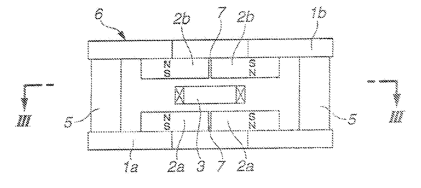
[0046]Two yokes were fixedly coupled by posts of the same magnetic material as the yokes to define a space of 10 mm between the magnets. An arm having a moving coil of copper wire wound thereon was inserted into the space, constructing a VCM as shown in FIGS. 4A and 4B. The torque of VCM was measured with the results shown in FIG. 11.

example 2

[0047]A Nd—Fe—B sintered magnetizable block (N48M by Shin-Etsu Chemical Co., Ltd.) was machined into rectangular prisms of 20.2 mm×12.4 mm×6 mm. Two pieces were arranged in a straight serial contiguous array and adhesively attached to a yoke of carbon steel having a thickness of 5 mm. They were magnetized in a thickness direction by means of a magnetizer so that N and S poles of serially arranged magnet pieces alternated along the yoke, completing a VCM as shown in FIGS. 5A and 5B. The assembly process was otherwise the same as in Example 1. The torque of VCM was measured with the results shown in FIG. 11.


PUM

PropertyMeasurementUnit
thicknessaaaaaaaaaa
rotational speedaaaaaaaaaa
shapeaaaaaaaaaa

Abstract

A magnet of rectangular prism of parallelepiped prism shape is disposed on a yoke having a triangle shape or a frusto-triangular shape to construct a magnetic circuit for a voice coil motor. The magnetic circuits facilitate positioning and holding of a moving coil, and the voice coil motor is improved in positioning precision of a magnetic head.

Description

CROSS-REFERENCE TO RELATED APPLICATION[0001]This non-provisional application claims priority under 35 U.S.C. §120 as a Divisional application of co-pending application Ser. No. 12 / 051,700, filed on Mar. 19, 2008, which claims priority under 35 U.S.C. §119(a) on Patent Application No. 2007-072789 filed in Japan on Mar. 20, 2007. The entire contents of all aforementioned applications are hereby incorporated by reference.TECHNICAL FIELD[0002]This invention relates to voice coil motors for head positioning in magnetic disk units, and magnetic circuits for use therein.BACKGROUND OF THE INVENTION[0003]In general, a hard disk unit includes a medium having a magnetic recording film deposited thereon, a spindle motor for rotating the medium at a predetermined rotational speed, a magnetic head for writing and reading information data, a voice coil motor (VCM) for driving the magnetic head, a controller and the like. The recent drastic price competition among manufacturers imposes a demand for...

Claims


Application Information

Patent Timeline
Patent Type & Authority Applications(United States)
IPC IPC(8): G11B5/55
CPCG11B5/5569H02K1/06H02K33/18G11B21/02
Inventor YAMADA, HIROYUKIKATO, DAIKINAGAMIYA, KEIJI
Owner YAMADA HIROYUKI
Why Eureka
Try Eureka