
Electromagnetic coupling

a technology of electromagnetic coupling and electrical line, which is applied in the direction of coupling devices, multiple-port networks, electrical apparatus, etc., can solve the problems of high failure rate, difficult direct connection, and difficult manufacturing of direct connections, and achieves simple and more secure interconnection, high power capability, and low profile

Inactive Publication Date: 2005-02-01
RAYTHEON CO
View PDF15 Cites 254 Cited by
  • Summary
  • Abstract
  • Description
  • Claims
  • Application Information

AI Technical Summary

Benefits of technology

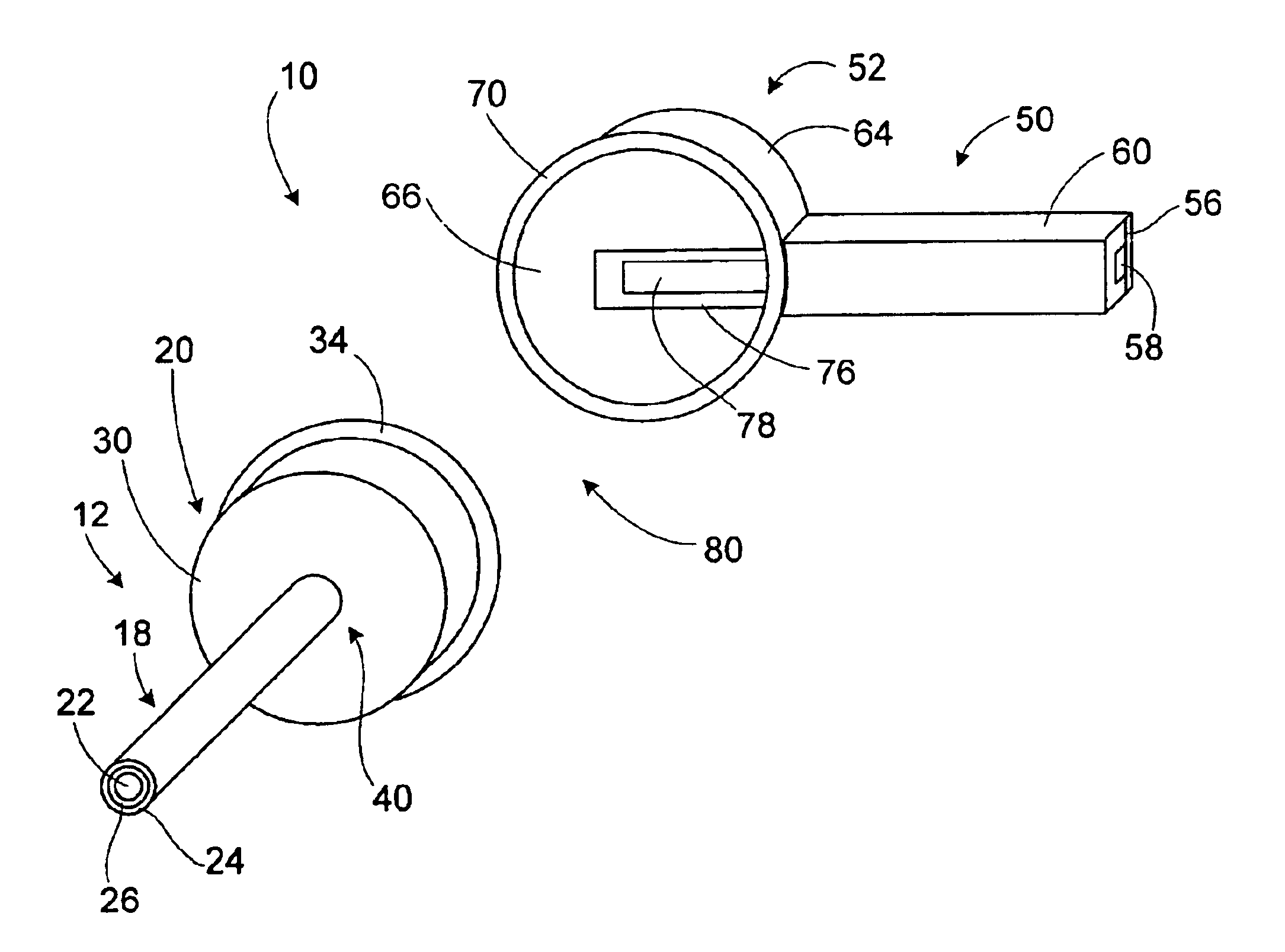
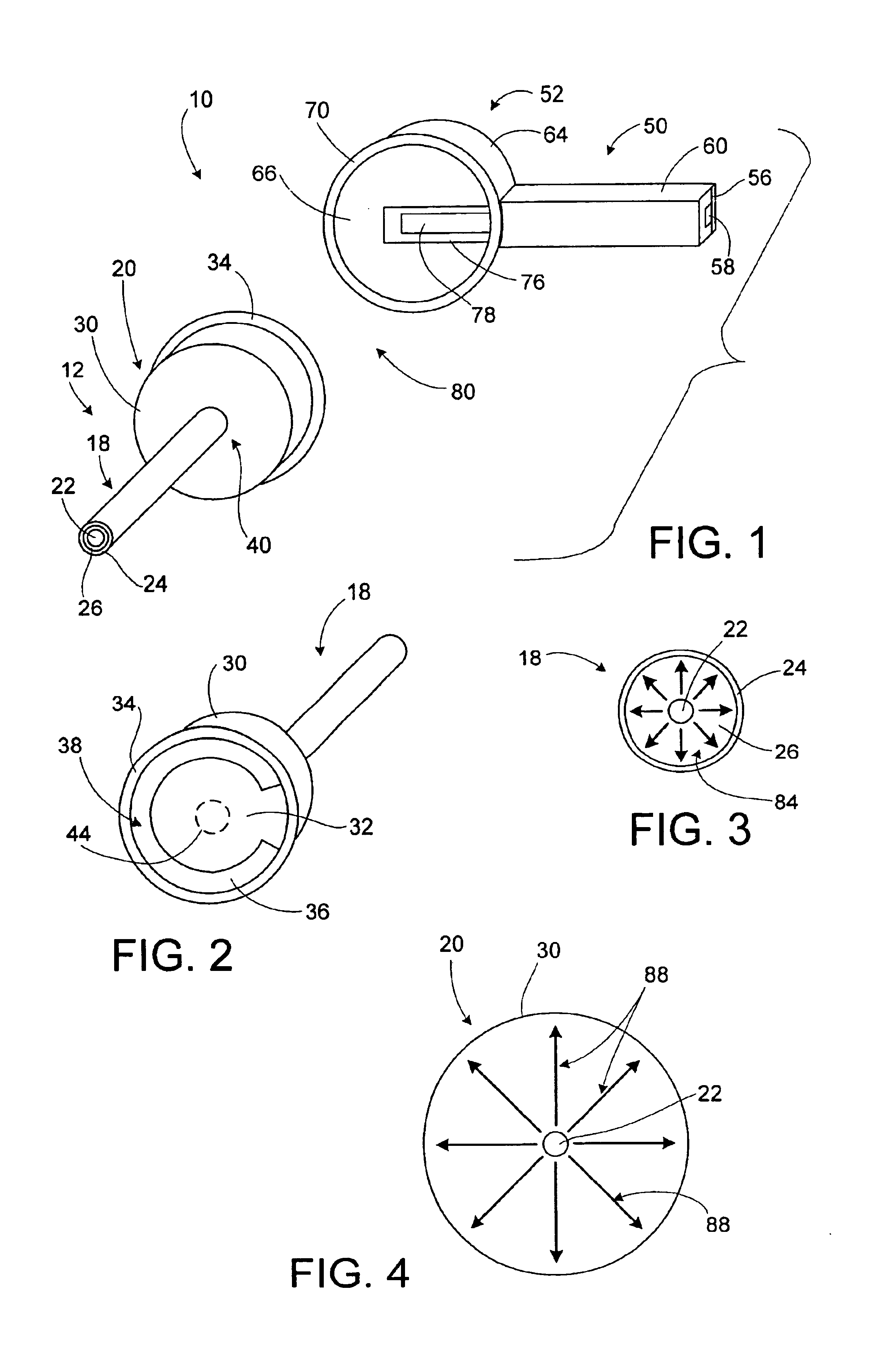
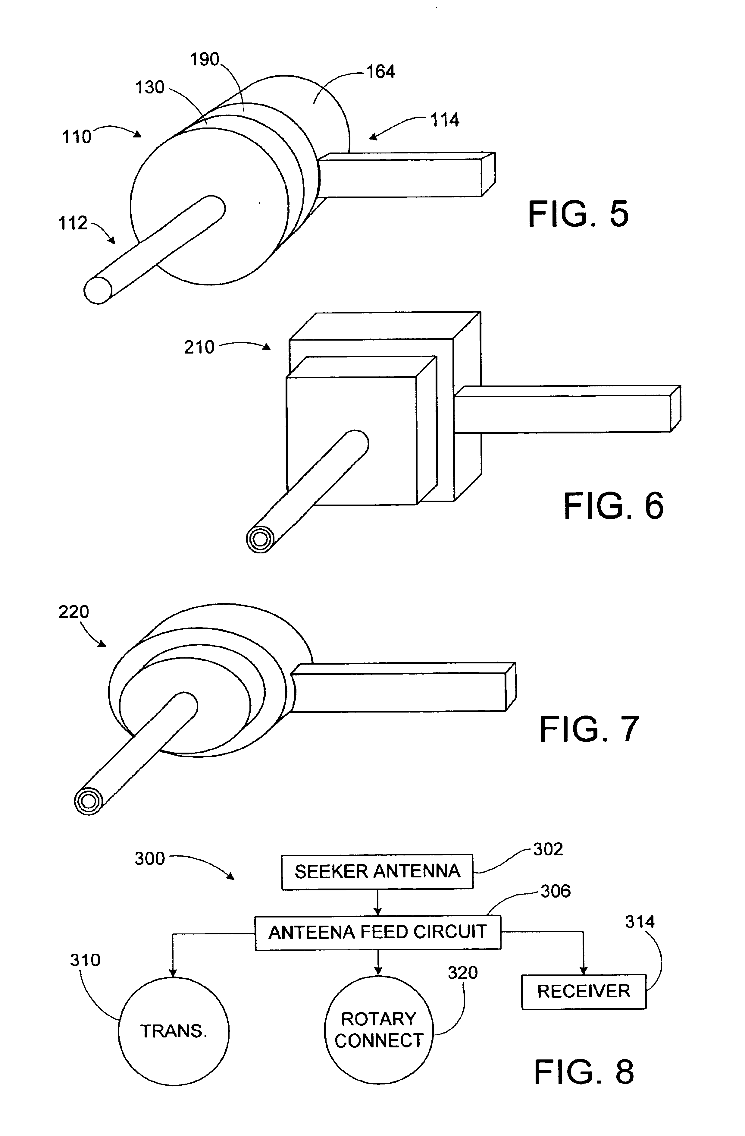
An electrical connection from coaxial cable to suspended air stripline (SAS), to stripline, or to microstripline, utilizes an electromagnetic-coupled cavity-backed slot. This allows high power capability, lower profile, and a simpler and more secure interconnection, when compared to prior direct connection methods. One of the conductors is attached to a ground plane which is adjacent to a resonant slot. The ground plane and the slot are enclosed in a conductive cavity. Electrical signals through the conductor excites a response in the slot, which in turn, induces a signal in the other conductor, making for a contactless electrical connection between the two conductors. The connection may involve a rotary joint allowing one of the conductors, for example, the coaxial cable, to rotate relative to the other conductor.

Problems solved by technology

Electrical connection for the inner conductor from coaxial line to suspended air stripline or conventional stripline is very difficult because of the small size of the inner conductor of a typical stripline circuit.
Such direct connections may be difficult to manufacture.
Furthermore, due to the small sizes involved, such connections may involve high rates of failure.
Another difficulty is that the small sizes of such connections may limit the power that they can handle.

Method used


Image

  • Electromagnetic coupling
  • Electromagnetic coupling
  • Electromagnetic coupling

Examples


Embodiment Construction

An orthogonal electrical coupling relies on electromagnetic coupling for the inner connection, as opposed to direct contact between conductors. A conductor on one of the lines is connected to a ground plane which is adjacent to a resonant slot. Microwave energy is coupled to the slot, thereby exciting the slot. A second conductor is on the opposite side of the ground plane from the first conductor. Microwave energy from the excited resonant slot passes to the second conductor, thereby allowing contactless electrical interconnection between the first conductor and the second conductor. This coupling through the resonant slot may in general be any of a number of transmission modes. However, the coupling may emphasize certain modes of propagation relative to other possible modes of propagation. Specifically, the ground plane and slot may be enclosed in a cavity that is of a size such that the cavity does not support any natural mode propagation inside the cavity. Instead, the coupling ...


PUM


Abstract

An orthogonal electrical coupling relies on electromagnetic coupling for the inner connection, as opposed to direct contact between conductors. A conductor on one of the lines is connected to a ground plane which is adjacent to a resonant slot. Microwave energy is coupled to the slot, thereby exciting the slot. A second conductor is on the opposite side of the ground plane from the first conductor. Microwave energy from the excited resonant slot passes to the second conductor, thereby allowing contactless interconnection between the first conductor and the second conductor. The coupling may emphasize certain modes of propagation relative to other possible modes of propagation. Specifically, the ground plane and slot may be enclosed in a cavity of a size such that the cavity does not support any natural mode propagation inside the cavity. Instead, the coupling may have a cavity in which a transverse electromagnetic (TEM) mode is propagated.

Description

TECHNICAL FIELDThe invention relates to interconnections between electrical lines, and in particular to electromagnetic couplings, such as for use in transitions in radar seeker antennas.DESCRIPTION OF THE RELATED ARTCoaxial line to suspended air stripline (or to convention stripline and / or microstripline) transitions are often used in radar seeker antennas. Conventional orthogonal transitions consist of brute force electrical contacts for both inner and outer conductors. Electrical connection for the inner conductor from coaxial line to suspended air stripline or conventional stripline is very difficult because of the small size of the inner conductor of a typical stripline circuit. Direct electrical connections involve, for example, soldering or otherwise connecting the coaxial conductors to the stripline conductors, or to mating electrical connectors. Such direct connections may be difficult to manufacture. Furthermore, due to the small sizes involved, such connections may involv...

Claims


Application Information

Patent Timeline
Patent Type & Authority Patents(United States)
IPC IPC(8): H01P5/08H01P1/06
CPCH01P5/085H01P1/066H01P5/08
Inventor PARK, PYONG K.
Owner RAYTHEON CO
Learn More