
Sheet post-processing device and image forming apparatus having the same

a post-processing device and image forming technology, applied in electrographic processes, instruments, transportation and packaging, etc., can solve the problems of difficulty in accurately folding the sheet stack at the desired folding point, and achieve the effect of simple drive control, and reducing the size and cost of the apparatus

Inactive Publication Date: 2005-01-25
NISCA KK +1
View PDF10 Cites 5 Cited by
  • Summary
  • Abstract
  • Description
  • Claims
  • Application Information

AI Technical Summary

Benefits of technology

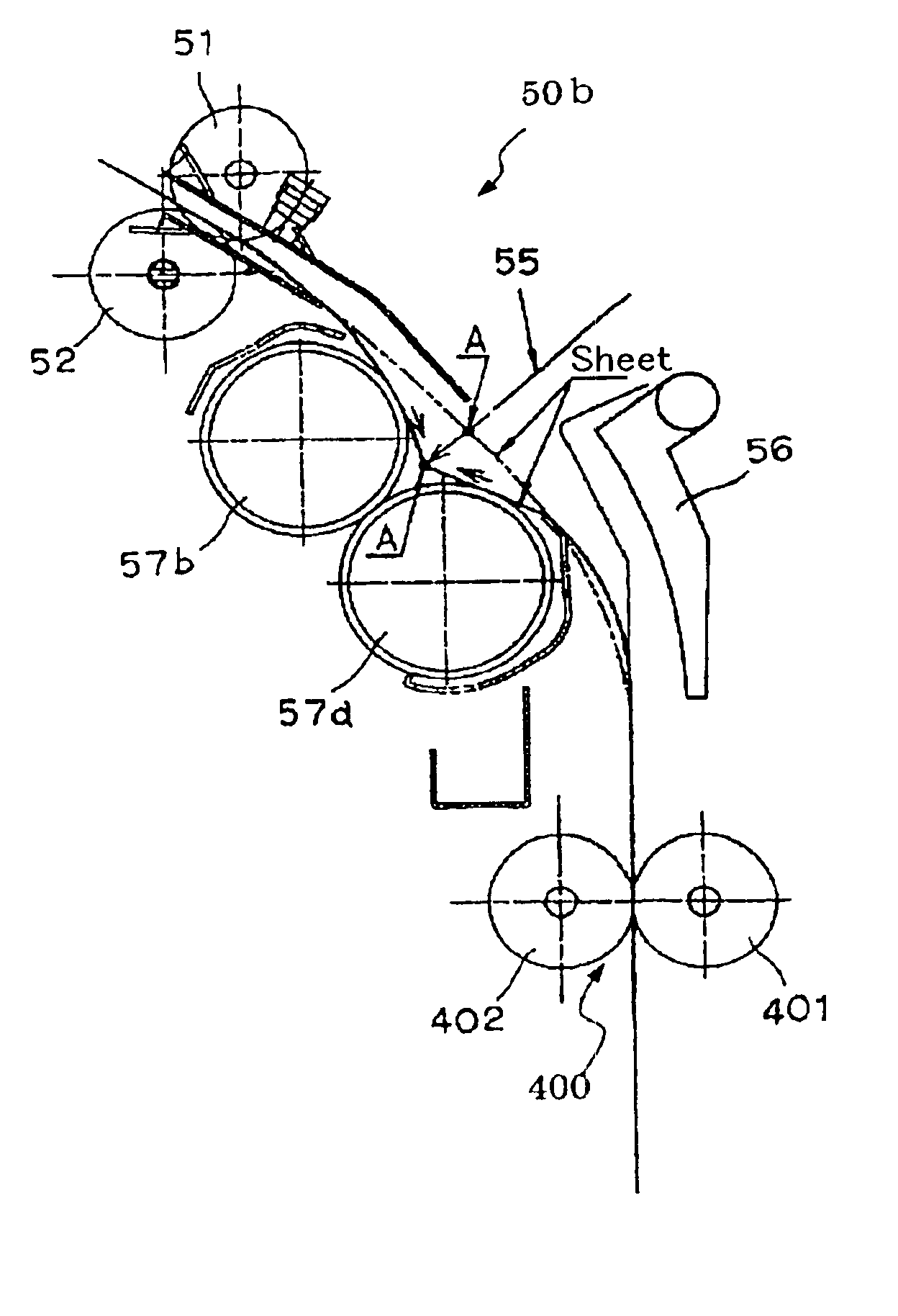
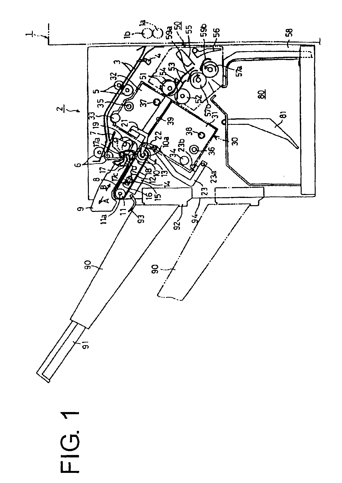
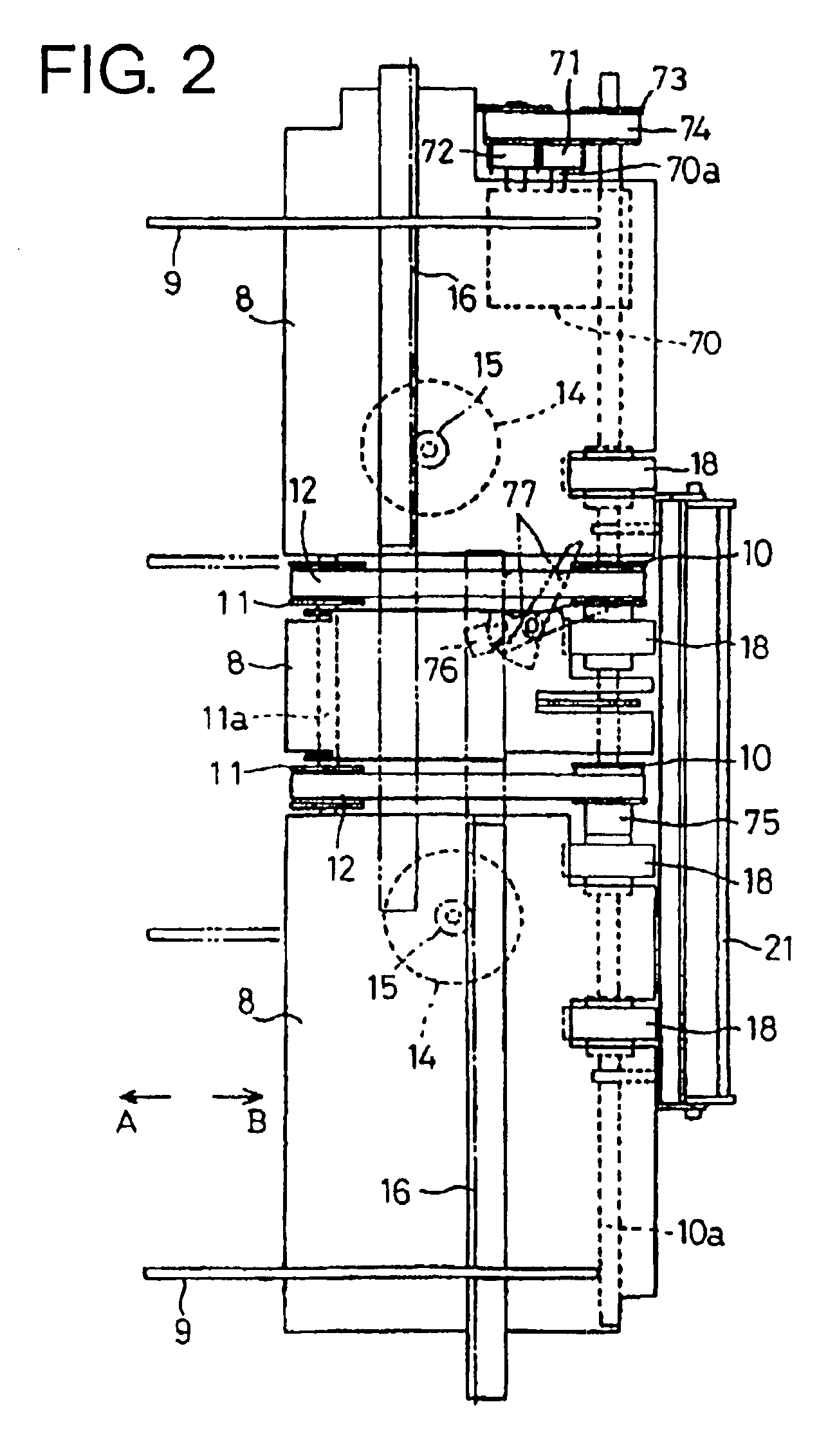
According to the sheet post-processing apparatus and image forming apparatus of the present invention, when the sheet pushing member (pushing plate) pushes and folds the sheet at the center thereof, the first load means (a pair of stack transport rollers) and the second load means (a lever for holding the sheet or a sheet holding mechanism provided with rollers) apply loads on the upstream and downstream sides of the sheet. When the sheet pushing means pushes the sheet, the folding rotating bodies (folding rollers) nip the sheet in a state that the sheet is pulled toward the upstream and the downstream sides of the sheet with the same tension. Therefore, it is possible to fold the sheet precisely without shifting an actual folding position from the predetermined folding position. Specifically, it is adjusted so that the load applied by the first load means and the load applied by the second load means are equivalent to minimize the shift of the actual folding position.
In the sheet post-processing apparatus and image forming apparatus of the present invention, the sheet transport means may function as at least one of the first load means and the second load means, thereby making a configuration of the apparatus simple and reducing a cost.

Problems solved by technology

Therefore, there is a problem in which it is difficult to accurately fold the sheet stack at a desired folding point.

Method used


Image

  • Sheet post-processing device and image forming apparatus having the same
  • Sheet post-processing device and image forming apparatus having the same
  • Sheet post-processing device and image forming apparatus having the same

Examples


Embodiment Construction

Hereunder, embodiments of the invention will be explained with reference to the accompanying drawings. A main configuration of a copier will be explained as an example of an image forming apparatus equipped with a sheet post-processing apparatus having a folding unit (sheet post-processing apparatus) for folding a sheet according to the invention with reference to FIG. 18.

A main unit 1 of a copier 20 is provided with a platen 906 as storage means (original tray), light source 907, lens system 908, sheet supply means (sheet feeder 909) and image forming means (image forming unit 902). An original automatic document feeder 940 is disposed at an upper portion of the main unit 1 for automatically feeding a original D to the platen 906.

The sheet feeder 909 comprises cassettes 910 and 911 detachably mounted to the main unit 1 for storing sheets S for recording, and a deck 913 arranged on a pedestal 912. The image forming unit 902 includes a photosensitive drum 914 having a cylindrical sha...


PUM

PropertyMeasurementUnit
thicknessaaaaaaaaaa
diameteraaaaaaaaaa
movementaaaaaaaaaa

Abstract

A sheet post-processing apparatus includes a pair of folding rollers for folding a transported sheet stack by rotation while nipping the sheet stack, a pushing plate for pushing the transported sheet stack into the folding rollers by advancing and retreating relative to the folding rollers, a stack transport upper roller and a stack transport lower roller (first load device) for applying a load to the pushing plate in pushing the sheet stack by contacting the sheet stack at an upstream side of the folding rollers, and sheet holding mechanism (second load device) having a lever for applying a load to the pushing plate in pushing the sheet stack by contacting the sheet stack at the downstream side of the folding rollers. An image forming apparatus is equipped with the sheet post-processing apparatus.

Description

BACKGROUND OF THE INVENTION AND PRIOR ART STATEMENTThe present invention relates to a sheet post-processing apparatus for folding a stack of sheets and an image forming apparatus equipped with the same.Conventionally, in an image forming apparatus such as a copier, printer, facsimile machine or machine combined thereof, there is a apparatus provided with a sheet post-processing device for folding a sheet discharged from an image forming apparatus to obtain a finished booklet.As such a conventional sheet post-processing device, there is a known device provided with a sheet folding mechanism having a plate-shaped pressing member for contacting a sheet along a folding position and a pair of rotating bodies for drawing in the sheet using the plate-shaped pressing member. FIG. 19 shows an example of such a sheet folding mechanism. A stack of sheets to be folded is transported to a folding position by a pair of stack transport rollers (51 and 52), and the stack stays there in a state that...

Claims


Application Information

Patent Timeline
Patent Type & Authority Patents(United States)
IPC IPC(8): G03G15/00B65H37/06B65H45/24
CPCB65H45/18G03G15/6538G03G2215/00877
Inventor FUKASAWA, EIJISATO, KOUKI
Owner NISCA KK
Learn More