
Hydraulic control system for automatic transmission

a technology of hydraulic control system and automatic transmission, which is applied in the direction of gearing control, gearing elements, gearing, etc., can solve the problems of large structure of conventional hydraulic control system, failure of valves, and large number of linear solenoid valves, and achieve the effect of reliably cutting off the supply of engagement pressure to the brake and a compact structur

Inactive Publication Date: 2005-01-25
AISIN AW CO LTD +1
View PDF3 Cites 4 Cited by
  • Summary
  • Abstract
  • Description
  • Claims
  • Application Information

AI Technical Summary

Benefits of technology

[0011]It is therefore an object of the present invention to provide a hydraulic control system for an automatic transmission, which has only a single pair of a linear solenoid valve and a control valve and, therefore, a more compact structure. The hydraulic control system is capable of reliably cutting off supply of the engagement pressure to the brake even if a failure occurs in the linear solenoid valve.
[0012]According to a first aspect of the present invention, with a simple structure wherein the linear solenoid valves and the control valves are grouped, the source pressure can be selectively obtained from either a first shift valve or a second shift valve so as to engage a required friction engagement element. This makes it possible to engage the friction engagement element for applying engine braking in relatively lower shift speeds and to engage the friction engagement element for establishing a shift speed in a relatively higher shift speed. In a lock-up stage, for example, if the first shift valve is in a second position and the second shift valve is in a first position, supply of the source pressure from the first and the second shift valves is interrupted. As a result, the friction engagement elements used for shifting may be reliably disengaged. As the output port can be selectively closed in accordance with the control pressure, the output of the engagement pressure in the lock-up stage is interrupted even if the source pressure for the engagement pressure is supplied to the control device owing to the failure in the first shift valve or the second shift valve. This allows the hydraulic control system to operate with fail-safe control.

Problems solved by technology

However, the conventional transmission requires a large number of relatively large size linear solenoid valves.
Accordingly, the structure of the conventional hydraulic control system is large, complicated and costly.
However, it is necessary to provide for the possibility that a failure may occur in those valves such as by valve sticking.
Provision for such a failure may complicate the structure of the circuit, and also complicate any modification aimed at reduction of the size of the hydraulic control system.

Method used


Image

  • Hydraulic control system for automatic transmission
  • Hydraulic control system for automatic transmission
  • Hydraulic control system for automatic transmission

Examples


Embodiment Construction

ic control unit to have a simple and compact structure.

[0033]In a hydraulic control system according to the second aspect of the invention, as the predetermined shift speed is a lock-up stage, supply of the engagement pressure to the friction engagement element such as the brake can be reliably interrupted in spite of a valve failure.

BRIEF DESCRIPTION OF THE DRAWINGS

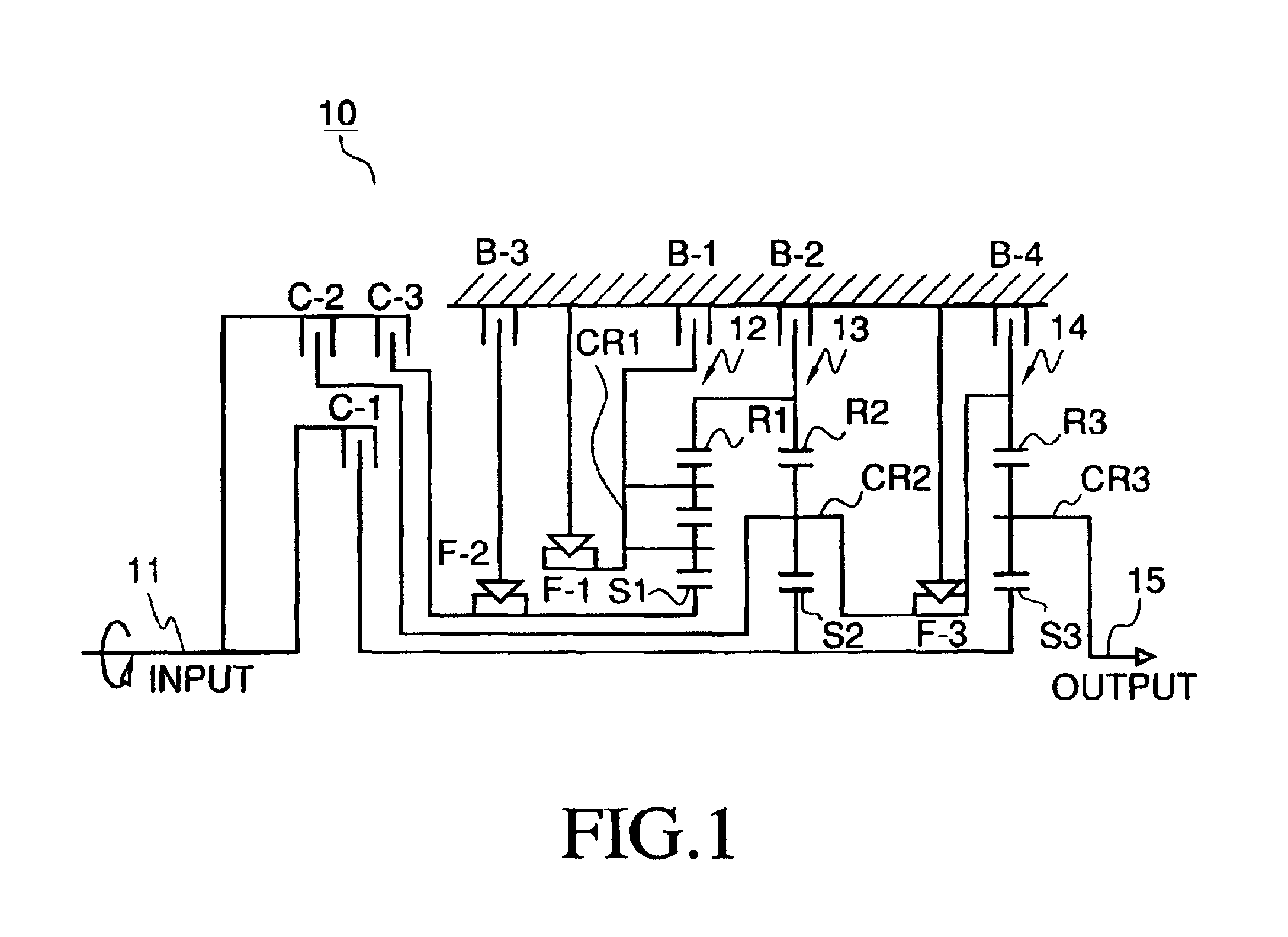
[0034]FIG. 1 is a schematic diagram representing an automatic transmission mechanism to which the present invention is applied;

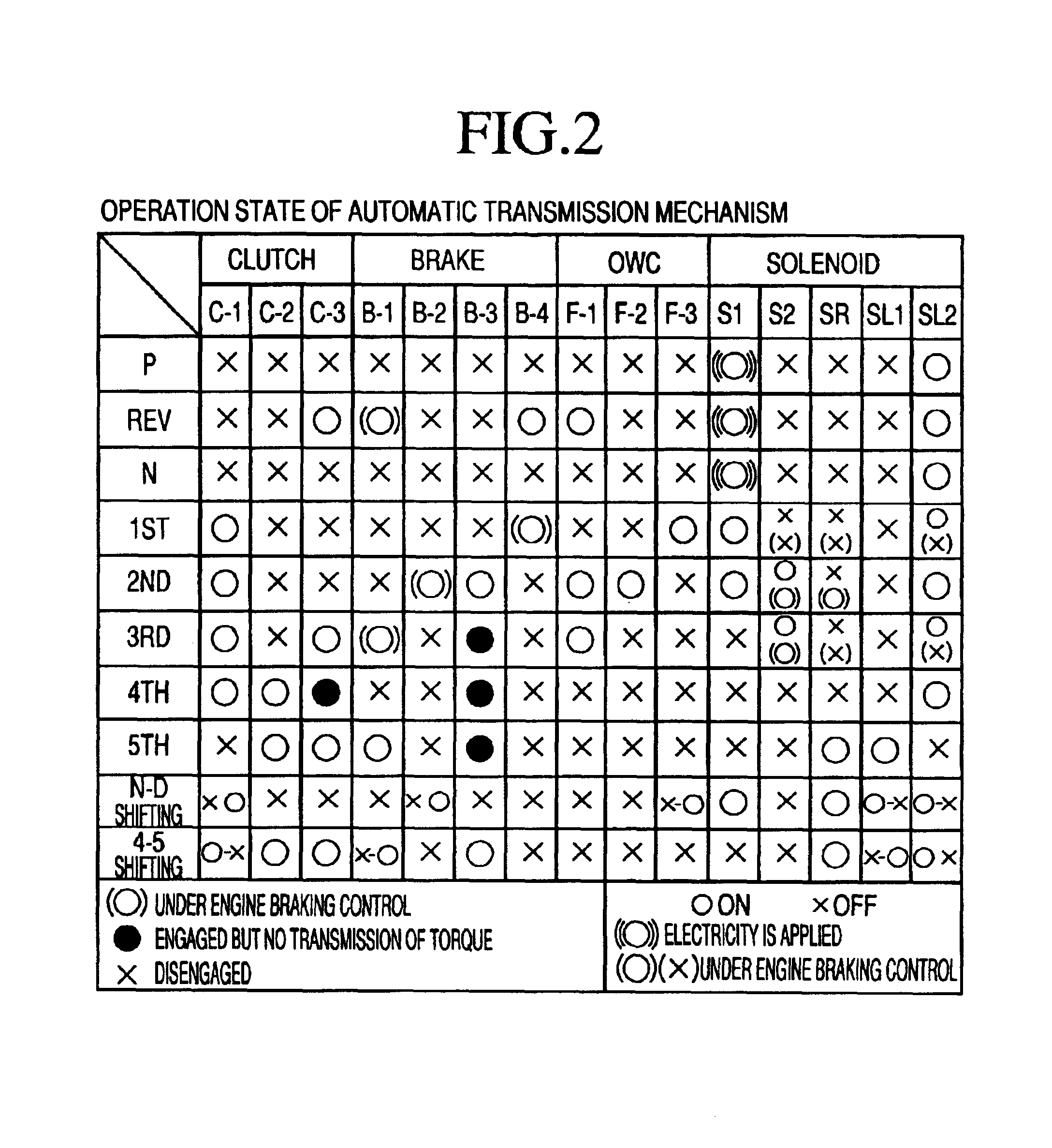
[0035]FIG. 2 is a table of operation states of the automatic transmission mechanism in drive (D) range; and

[0036]FIG. 3 is a schematic circuit diagram of a hydraulic control system for an automatic transmission in accordance with the present invention.

DETAILED DESCRIPTION OF PREFERRED EMBODIMENTS

[0037]A preferred embodiment of the present invention will now be described with reference to the drawings.

[0038]Referring to the table in FIG. 2, each of the marks (O), ♦, and (X), in columns for CLUTCH,...


PUM


Abstract

A hydraulic control system for an automatic transmission includes a 3-4 shift valve that outputs a source pressure through a first path for shift speeds lower than a fourth shift speed established by directly connecting an input shaft with an output shaft of the automatic transmission, i.e., third shift speed. The hydraulic control system further includes a clutch apply control valve that outputs a source pressure through a second path at a shift speed higher than the fourth shift speed, i.e., fifth speed. The 3-4 shift valve and the clutch apply control valve serve to interrupt supply of the source pressure through the first path and the second path, respectively, in the fourth speed or the lock-up stage.

Description

CROSS-REFERENCE TO RELATED APPLICATION[0002]This application claims, under 35 USC 119, priority of Japanese Application No. 2002-191523 filed Jun. 28, 2002.INCORPORATION BY REFERENCE[0003]The disclosure of Japanese Patent Application No. 2002-191523 filed on Jun. 29, 2002 including the specification, drawings and abstract are incorporated herein by reference in its entirety.BACKGROUND OF THE INVENTION[0004]1. Field of Invention[0005]The present invention relates to a hydraulic control system for an automatic transmission. More specifically, the present invention relates to a hydraulic control system for an automatic transmission, which cuts supply of the source pressure used for engaging a brake in a lock-up stage where an input shaft and an output shaft are directly connected.[0006]2. Description of Related Art[0007]In a conventional hydraulic control system for an automatic transmission (hereinafter simply “hydraulic control system”) a plurality of shift valves are selectively cha...

Claims


Application Information

Patent Timeline
Patent Type & Authority Patents(United States)
IPC IPC(8): F16H61/12F16H61/21F16H61/00F16H61/68F16H61/684F16H61/686
CPCF16H61/12F16H2061/1264F16H2061/122F16H61/686
Inventor FUJIMINE, TAKUYAFUKATSU, AKIRANODA, KAZUYUKIANDO, MASAHIKONOZAKI, KAZUTOSHIKANADA, TOSHIKI
Owner AISIN AW CO LTD
Learn More