
Electrochemical device and method for producing an electrochemical unit for an electrochemical device

Active Publication Date: 2018-04-12
EKPO FUEL CELL TECH GMBH
View PDF0 Cites 1 Cited by
  • Summary
  • Abstract
  • Description
  • Claims
  • Application Information

AI Technical Summary

Benefits of technology

The present invention provides an electrochemical device that can seal off flow fields and prevent the occurrence of parasitic flows. This simplifies the device's construction and increases its reliability.

Problems solved by technology

Even if electrochemical reactions in the region of the edge channel are suppressed by the application of an edge reinforcing arrangement, the media that still flow through the edge channel are not available for an electrochemical reaction.
Further, application of the edge reinforcing arrangement is associated with an increased cost for production and assembly.

Method used


Image

  • Electrochemical device and method for producing an electrochemical unit for an electrochemical device
  • Electrochemical device and method for producing an electrochemical unit for an electrochemical device
  • Electrochemical device and method for producing an electrochemical unit for an electrochemical device

Examples


first embodiment

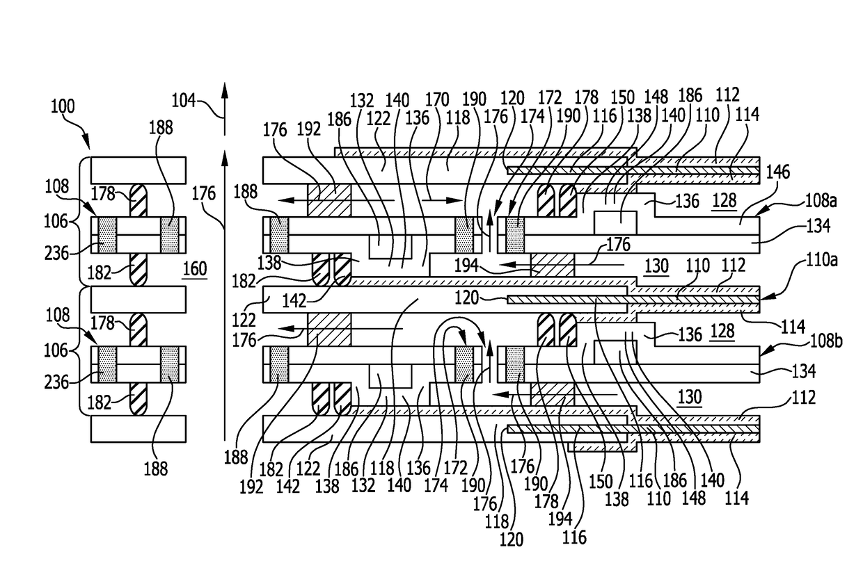
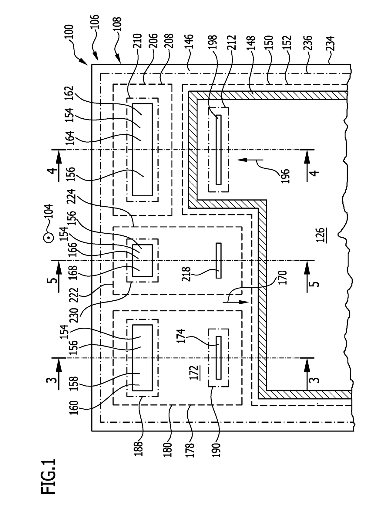
[0243]An alternative embodiment of an electrochemical device 100 of this kind, illustrated in FIGS. 6 to 12, differs from the first embodiment illustrated in FIGS. 1 to 5 in that the anode-side flow field seal elements 150 each abut in a fluid-tight sealing manner against a cathode-side flow field seal element 142 of a bipolar plate 108 that lies above it, as seen in the stacking direction 104, in a fluid-tight sealing manner (see FIGS. 8 to 12).

[0244]To enable this, the mutually facing edge webs 132, 148 of two bipolar plates 108a and 108b that succeed one another as seen in the stacking direction 104, and which are each arranged on the mutually opposite sides of the same membrane electrode assembly 110, are arranged congruently with one another—as seen in the stacking direction 104—while the edge webs 132 and 148 of the same bipolar plate 108a or 108b, just as in the first embodiment illustrated in FIGS. 1 to 5, are still arranged offset from one another in certain areas, in an of...

second embodiment

[0279]Unlike the second embodiment that is illustrated in FIGS. 6 to 12, in this case it is preferably provided for the flow field seal elements 142, 150 produced on the bipolar plate layers 134 and 146 and / or the channel seal elements 178, 182 produced on the bipolar plate layers 134 and 146 to overlap with the join lines 188, 190, 210, 212, 230 and / or 236 at which the bipolar plate layers 134 and 146 are joined to one another by adhesion, which makes possible a more compact structure of the bipolar plates 108 and hence of the electrochemical device 100 as a whole in the region of the said seal elements.

[0280]Otherwise, the fourth embodiment of the electrochemical device 100 that is illustrated in FIG. 20 corresponds, as regards its structure, functioning and production, to the second embodiment illustrated in FIGS. 6 to 12, so in this respect reference is made to the description thereof above.

[0281]FIGS. 21 and 22 show a comparison of the space needed for a seal structure accordin...


PUM


Abstract

An electrochemical device is provided that includes a stack of a plurality of electrochemical units that succeed one another in a stacking direction and each include an electrochemically active membrane electrode assembly, at least one gas diffusion layer and a bipolar plate having at least one flow field, in which at least one flow field is sealed off simply and reliably and the occurrence of parasitic flows is prevented, wherein at least one bipolar plate has at least one edge web, which borders a flow field of the bipolar plate and is in contact with a gas diffusion layer adjacent to the bipolar plate, and wherein the electrochemical device further includes at least one flow field seal element that seals off the flow field bordered by the edge web and is in contact with the edge web and in contact with the gas diffusion layer.

Description

CROSS-REFERENCE TO RELATED APPLICATIONS[0001]This application is a continuation of International Application No. PCT / EP2016 / 062675 filed Jun. 3, 2016, which claims priority to German Patent Application No. 10 2015 109 393.6, filed Jun. 12, 2015, both of which are incorporated herein by reference.FIELD OF DISCLOSURE[0002]The present invention relates to an electrochemical device that includes the following:a stack of a plurality of electrochemical units that succeed one another in a stacking direction and each include an electrochemically active membrane electrode assembly, at least one gas diffusion layer and a bipolar plate having at least one flow field for at least one fluid medium.[0003]An electrochemical device of this kind may in particular take the form of a fuel cell stack or an electrolyzer.BACKGROUND[0004]In fuel cell stacks and electrolyzers, different media are guided in different levels of an electrochemical unit and, depending on the construction, also in different reg...

Claims


Application Information

Patent Timeline
IPC IPC(8): H01M8/0273H01M8/0258H01M8/1004H01M8/1018H01M8/242H01M8/2483C25B9/08C25B9/20C25B9/19
CPCH01M8/0273H01M8/0258H01M8/1004H01M8/1018H01M8/242H01M8/2483C25B9/08C25B9/20H01M2008/1095C25B9/77Y02E60/50C25B9/73C25B9/19
Inventor STAHL, PETERKRAFT, JUERGENGOETZ, MICHAEL
Owner EKPO FUEL CELL TECH GMBH
Learn More