
Photodetector using photomultiplier and gain control method

Active Publication Date: 2007-02-22
HAMAMATSU PHOTONICS KK
View PDF2 Cites 2 Cited by
  • Summary
  • Abstract
  • Description
  • Claims
  • Application Information

AI Technical Summary

Benefits of technology

[0010] The present invention has been made to resolve the above problems and an object thereof is to provide a photodetector using a photomultiplier that can realize a gain adjustment for each of electron multiplier channels respectively assigned to a plurality of light incidence regions partitioned on an entrance face plate in a more compact structure, and a gain control method for the electron multiplier channels in the photomultiplier applied to the photodetector.
[0016] In the photodetector according to the present invention, the control plates, constituting the n-th dynode plate, are supported in a state of being sandwiched, via insulators, by the (n−1)-th dynode plate and the (n+1)-th dynode plate. By this arrangement, each of the control plates making up the n-th dynode plate can be set to an arbitrary potential, thereby enabling realization of a gain adjustment for each channel in a more compact structure.
[0017] In the photodetector according to the present invention, the photomultiplier may further comprise a protection electrode provided between the stem and the dynode unit. This protection electrode supports the entirety of the dynode unit via an insulator and is provided with a plurality of through holes each housing the associated one of the anodes individually. In particular, a diameter of each dynode side opening of the protection electrode is preferably narrower than a diameter of each stem side opening of the protection electrode. In this case, since the trajectories of secondary electrons emitted from the final stage of dynode plate in the dynode unit to the anodes are respectively converged every anode, crosstalk among the anodes corresponding to the respective channels is reduced effectively.
[0018] In the photodetector according to the present invention, the photomultiplier may further comprise a focusing electrode disposed between the photocathode and the dynode unit. In this case, the focusing electrode is preferably provided with a plurality of through holes each arranged at a position corresponding to the associated one of the channels assigned to the plurality of light incidence regions partitioned on the entrance face plate. Since photoelectrons emitted from a certain region of the entrance face plate will then arrive at a high probability at an electron multiplier hole, which, among the electron multiplier holes of the first dynode plate, corresponds to the channel assigned to the region from which the photoelectrons are emitted, crosstalk among the electron multiplier channels is reduced effectively.
[0019] Accordingly, the photodetector according to the present invention, due to such an arrangement, enables each of the control plates constituting the n-th dynode to be set to an arbitrary potential and thus the realization of gain adjustment for each electron multiplier channel in a more compact structure.

Problems solved by technology

The inventors have studied a conventional multi-anode photomultiplier as a photo-sensing device in detail, and as a result, have found problems as follows.
That is, a limit to making the photomultiplier itself compact and the resolution of a photodetector itself including the same could not be improved.
However, since the electron multiplier holes for channels in each dynode are provided with a common potential, the gain cannot be adjusted in each channel.
Applications are thereby restricted significantly.
Additionally, in consideration of applications of the multi-anode photomultiplier to high energy physics and other scientific technological fields (digital signal processing applications) as well as fluorescence analysis, blood analysis, drug development, and other analysis technologies in the field of biotechnology (analog signal processing applications), it is inadequate to simply make the gain uniformity substantially uniform among the respective channels to adjust the detection efficiency of the respective channels.

Method used


Image

  • Photodetector using photomultiplier and gain control method
  • Photodetector using photomultiplier and gain control method
  • Photodetector using photomultiplier and gain control method

Examples


Embodiment Construction

[0038] In the following, embodiments of a photodetector and a gain control method according to the present invention will be explained in detail with reference to FIGS. 1-6, 7A-8B, 9-10, 11A-15B and 16. In the explanation of the drawings, constituents identical to each other will be referred to with numerals identical to each other without repeating their overlapping descriptions.

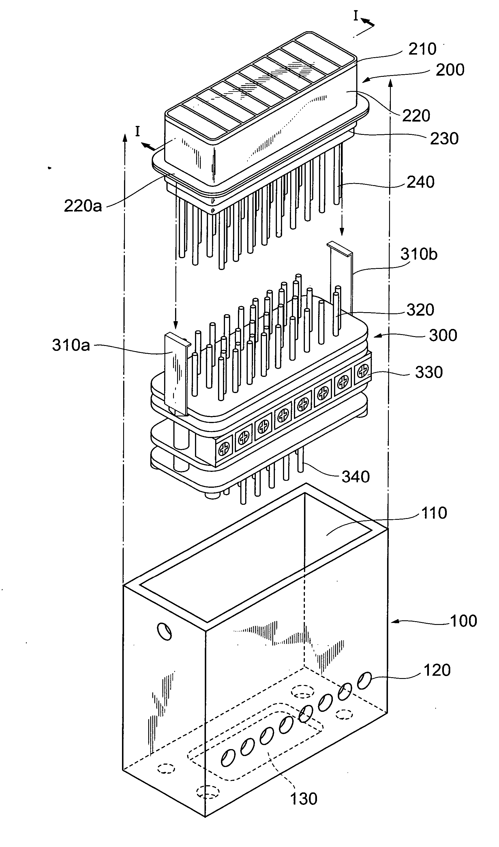
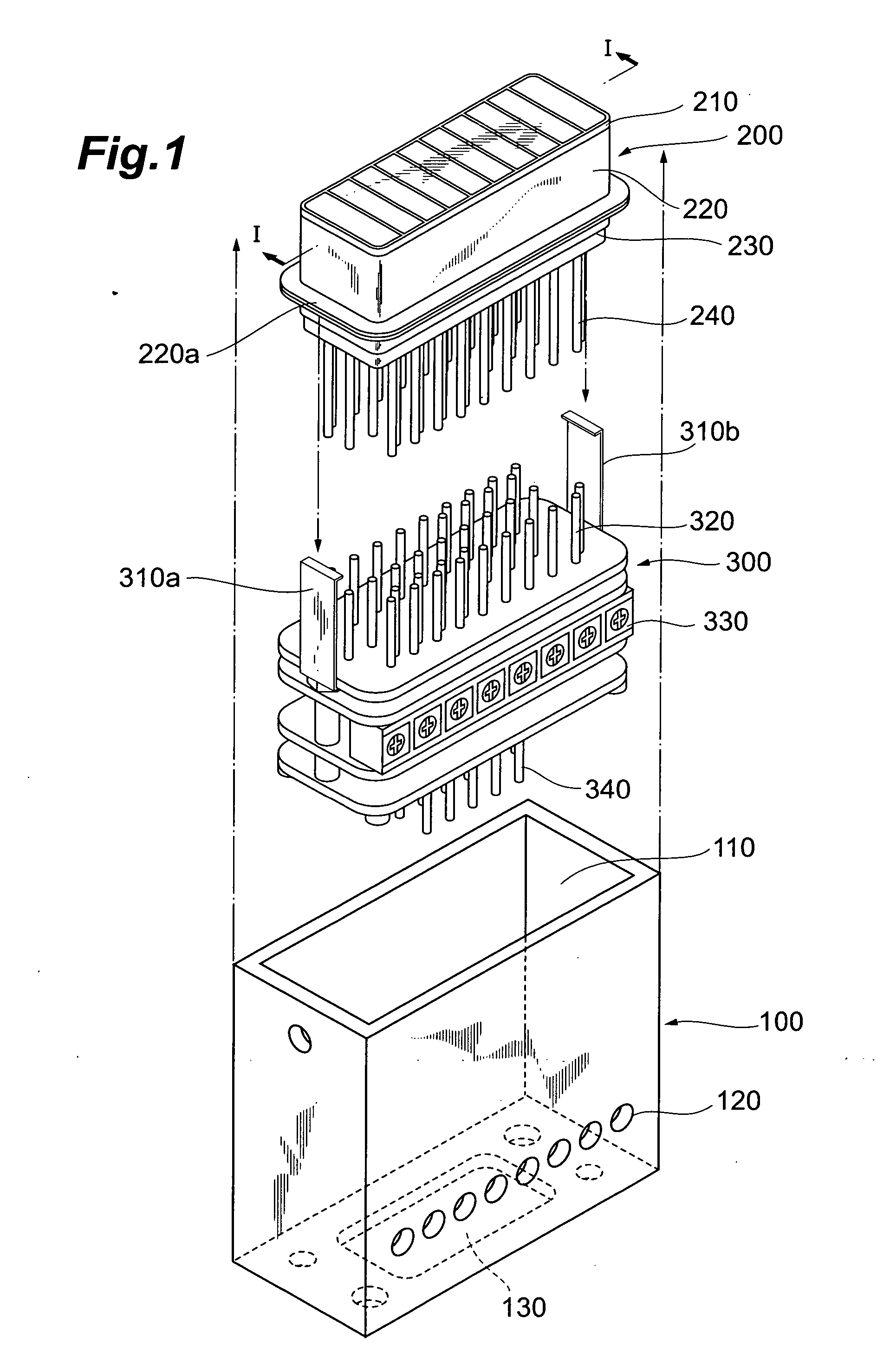
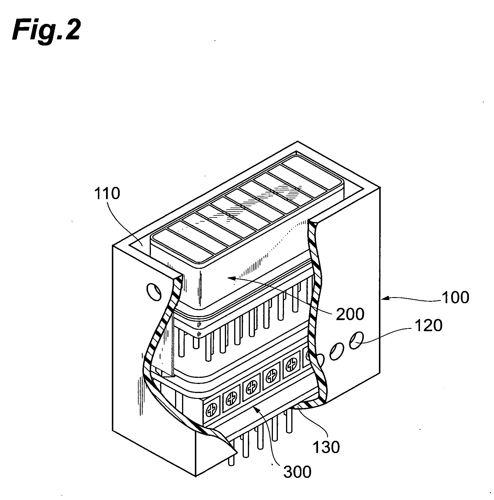
[0039]FIG. 1 shows an assembly process diagram of a configuration of a photodetector according to the present invention, and FIG. 2 shows a partially broken-away view of a configuration the photodetector according to the present invention. In the following embodiment, as a photomultiplier applied to a photodetector, an 8-channel multi-anode type of photomultiplier, in which an entrance face plate is partitioned into eight effective regions, will be explained.

[0040] As shown in FIG. 1, the photodetector, which is applied to the photodetector according to the present invention, comprises a case 100, a photo...


PUM


Abstract

The present invention relates to a photodetector that has a structure capable of realizing a wide range gain adjustment for each of electron multiplier channels respectively assigned to a plurality of light incidence regions of a multi-anode multiplier. The photodetector comprises a multi-anode photomultiplier, and a bleeder circuit unit. The multi-anode multiplier has a dynode unit constituted by N (an integer or no less than 3) dynode plates, and n-th (an integer of no less then 2) dynode plate is constituted by a plurality of control plates respectively corresponding to the multiplier channels. The bleeder circuit unit has a primary section setting each potential of a first to (n−1)-th and (n+1)-th to N-th dynode plates, and a secondary section for individually setting a potential of each control plate at any potential within the range wider than a potential difference between the (n−1)-th and (n+1) dynode plates. By expanding the potential setting range for the control plates rather than the potential difference between the dynode plates adjacent to the n-th dynode plate, the gain of each electron multiplier channel can be controlled by two digits or more.

Description

CROSS-REFERENCE TO RELATED APPLICATION [0001] This is a Continuation-In-Part application of the patent application Ser. No. 11 / 188,215 filed on Jul. 25, 2005 by the same Applicant, now pending.BACKGROUND OF THE INVENTION [0002] 1. Field of the Invention [0003] The present invention relates to a photodetector using a photomultiplier which enables electron multiplications in electron multiplier channels respectively assigned to a plurality of light incidence regions partitioned on an entrance face plate, and a gain control method for the electron multiplier channels in the photomultiplier applied to the photodetector. [0004] 2. Related Background of the Invention [0005] U.S. Pat. No. 5,077,504 discloses a photomultiplier having a single entrance face plate partitioned into a plurality of light incidence regions, and having a structure in which a plurality of electron multiplier sections (each constituted by an anode and a dynode unit comprising a plurality of dynode stages) prepared a...

Claims


Application Information

Patent Timeline
IPC IPC(8): H01J40/14
CPCH01J43/22H01J40/14H01J43/045
Inventor KATO, HISAKISHIMOI, HIDEKIHORIUCHI, KAZUYAUSHIZU, TOSHIAKI
Owner HAMAMATSU PHOTONICS KK
Learn More