Heat transfer ice cream scoop

a technology of ice cream scoops and ice cream, which is applied in the direction of ceramic shaping apparatuses, sweetmeats, manufacturing tools, etc., can solve the problems of significant force required to push the utensils, and unsatisfactory known methods for heating such utensils, so as to facilitate the removal of frozen products and maximize heat capacity and thermal conductivity of materials

Inactive Publication Date: 2005-01-25
HERBERT WILLIAM J
View PDF20 Cites 18 Cited by
  • Summary
  • Abstract
  • Description
  • Claims
  • Application Information

AI Technical Summary

Benefits of technology

According to one aspect of the present invention, a new and improved ice cream scoop is provided that combines the optimum heat capacity and thermal conductivity of the material of the ice cream scoop to facilitate the removal of the frozen product from the ice cream container.

Problems solved by technology

It is well known that a common problem with dispensing frozen products is that the utensil used to dispense the frozen product requires significant force in order to remove the frozen product from the frozen product container.
Because frozen ice cream is a “solid,” it requires significant force to push the utensil through the ice cream.
However, known methods for heating such a utensil have largely proven to be unsatisfactory.
The primary problem is in transferring sufficient heat to the portion of the utensil that contacts the frozen product (generally, the scoop portion).
A problem with this method is that there is insufficient heat capacity in the scoop to provide for a high scooping performance with hard ice cream or the time required to heat the entire ice cream scoop mass would be unduly long.
In particular, such scoops lack the required mass of fluid and / or scoop material to establish the required heat capacity.
However, Virkler does not teach the required values for heat capacity and thermal conductivity as discovered by applicant.
Thus, Virkler does not teach the critical parameters required for high scooping performance with hard ice cream.
Those powered by battery are well known to quickly lose the battery power.
Those powered by a power outlet are expensive to manufacture and awkward to use.
However, as with many of the alternatives noted above, such scoops do not provide a sufficiently high scooping performance with hard ice cream.
Such spades may also include a defrosting fluid in the handle but also fail to provide a sufficiently high scooping performance with hard ice cream.

Method used


Image

  • Heat transfer ice cream scoop
  • Heat transfer ice cream scoop
  • Heat transfer ice cream scoop

Examples


first embodiment

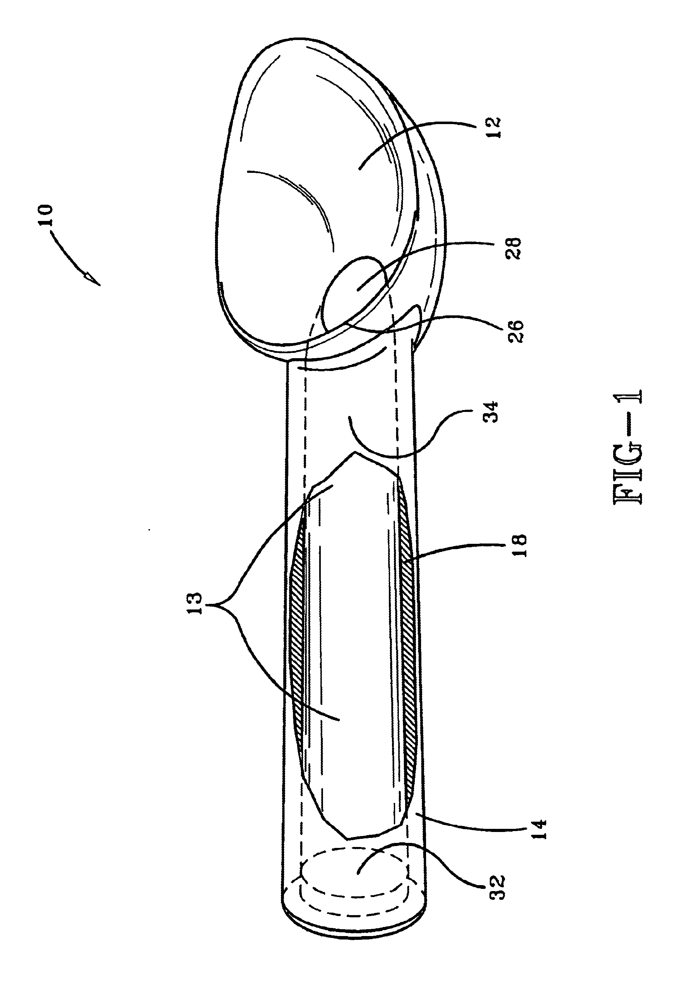
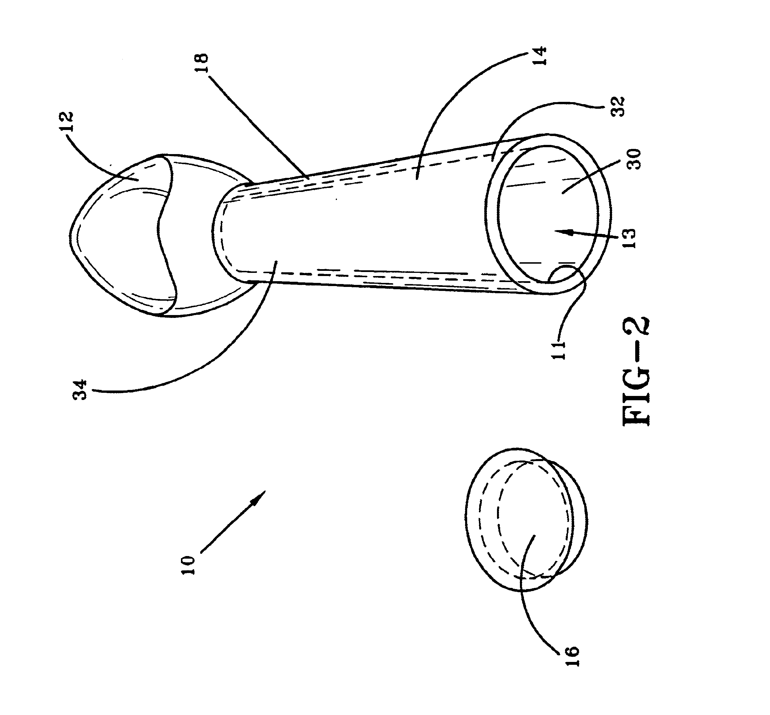
Referring now to the drawings wherein the showings are for purposes of illustrating a preferred embodiment of the invention only and not for purposes of limiting the same, FIGS. 1 and 2 show the present invention. A utensil 10 includes a scoop portion 12, that is preferably bowl shaped, and is adapted to scoop a frozen product from a frozen product container. The utensil 10 also includes a handle 14 having first and second ends 34, 32 respectively. The first end 34 may be connected to the scoop portion 12 as shown. Of course the handle 14 may be connected to the scoop portion 12 in any manner chosen with sound engineering judgment. The handle 14 preferably includes a hollow portion 11 thereby creating a fluid retention region 13 adapted to receive an associated fluid, such as water. This utensil may also include a cap 16 that is selectively connectable to the second end 32 of the handle and adapted to enclose the associated fluid within the fluid retention region 13 of the handle 14...

second embodiment

FIG. 3 along with FIGS. 1 and 2 show one version of the present invention. FIG. 3 shows a heat transfer member 20 consisting of a first end 22 and a second end 24. In the embodiment shown, the heat transfer member is heat pipe 20 but alternative heat transfer members are also possible as discussed further below. The heat pipe 20 is inserted into the handle 14 of the ice cream scoop 10 whereupon the first end 22 is further inserted into an aperture 28 at the base 26 of the scoop portion 12 to hold the heat pipe 20 in place during use. After the fluid retention region 13 is filled with hot or warm water, the cap 1 may be placed over the opening 30 at the end of the handle 14. However, it should be noted that a cap is not required. In other words, the fluid retention region 13 may be filled with fluid and then sealed. The heat transfer member 20 could still transfer heat from the fluid to the scoop portion 12. It should be noted that the heat pipe also removes heat from the handle 14 m...


PUM

PropertyMeasurementUnit
temperatureaaaaaaaaaa
heat capacityaaaaaaaaaa

Abstract

An ice cream scoop that optimizes the total heat capacity of the scoop by increasing the mass of the ice cream scoop and/or increasing the amount of liquid the ice cream scoop can hold there by creating a highly efficient ice cream scoop. A second embodiment of the present invention also allows for two methods of increasing the heat transfer from the heat source to the scoop portion. The first version utilizes a heat pipe that directs the heat flow directly to the location requiring the heat. The second version utilizes a highly conductive material that has a higher rate of conductivity than that of aluminum.

Description

I. BACKGROUND OF THE INVENTIONA. Field of InventionThis invention pertains to the art of methods and apparatuses for dispensing frozen products and more particularly to an ice cream scoop that incorporates an improved method and apparatus for transferring heat to the scoop portion of the ice cream scoop.B. Description of the Related ArtIt is well known that a common problem with dispensing frozen products is that the utensil used to dispense the frozen product requires significant force in order to remove the frozen product from the frozen product container. For example, when a user desires to remove frozen ice cream from an ice cream container, a utensil, such as a spoon or ice cream scoop, must be forced into and through the ice cream in order to remove a portion of ice cream. Because frozen ice cream is a “solid,” it requires significant force to push the utensil through the ice cream. This significant force is especially required for frozen products considered “hard” because the...

Claims


Application Information

Patent Timeline
Patent Type & Authority Patents(United States)
IPC IPC(8): A23G9/04A23G9/28A47J43/28
CPCA47J43/282
Inventor HERBERT, WILLIAM J.
Owner HERBERT WILLIAM J
Why Eureka
Try Eureka