
Airbag apparatus for a compact vehicle

a compact vehicle and airbag technology, applied in the field of compact vehicles, can solve the problems of complicated connection between the airbag and the inflator, the difficulty of ensuring a space for disposing the inflator, and the complicated configuration of the airbag

Inactive Publication Date: 2005-01-25
HONDA MOTOR CO LTD
View PDF8 Cites 17 Cited by
  • Summary
  • Abstract
  • Description
  • Claims
  • Application Information

AI Technical Summary

Benefits of technology

In view of such circumstances, an object of the present invention is to provide an airbag apparatus for a compact vehicle, in which the connection between the inflator and the airbag may be simplified while enabling simplification of the configuration of the airbag.
According to the structure described above, since the airbag is supported on the top bridge or on the steering handle, there is no obstacle in the direction of inflation and deployment when the airbag is inflated and deployed for restraining the operator behind the steering handle, whereby the configuration of the airbag may be simplified and the flexibility of the parts for arrangement around the steering handle may be increased. In addition, the inflator is stored in the pipe stem and the inflator may be arranged by effectively utilizing the space in the pipe stem. Furthermore, the pipe stem rotates integrally with the top bridge or with the steering handle. Thus, the structure of connection between the airbag and the inflator may be simplified.
In addition, according to the construction of the present invention the aforementioned airbag in the folded state is disposed along the aforementioned steering handle and stored in the handle cover for covering the steering handle. In this arrangement, the space for arranging the airbag in the folded state may be secured around the steering handle without a problem and the inflation and deployment of the airbag may be facilitated. Further, a specific cover for storing the airbag is not necessary, which contributes to reduction in the number of components.
In addition according to the present invention the aforementioned airbag is supported on the steering handle at a plurality of points spaced longitudinally with respect to the aforementioned steering handle. In this arrangement, the stability of the airbag in lateral direction of the compact vehicle is increased during inflation and deployment of the airbag, so that the restraining capability of the airbag for the operator may be improved.
In another embodiment, it is an object of the present invention to provide an airbag apparatus for a compact vehicle, which enables upsizing of a fuel tank if the fuel tank is located in front of the seat, and hence to enhance versatility by enabling an easy application to various compact vehicles.
According to the structure described above, since the airbag module is stored in the pipe stem being relatively small in diameter, it is easy to close the upper end of the pipe stem in a liquid-tight manner, so that the liquid-tight property is maintained when the inflator is not actuated, and the liquid-tight property is released as the airbag is inflated and deployed. Therefore, its antiweatherability may easily be enhanced. In addition, since the space for installing the airbag module does not affect on the capacity of the fuel tank in the case where the fuel tank is located in front of the seat, the fuel tank may be upsized, and it may easily be applied to various types of compact vehicles having a structure in which the pipe stem is rotatably supported by the head pipe. Therefore, the general-purpose properties may be enhanced.

Problems solved by technology

Thus, the configuration of the airbag is obliged to be complicated, and the arrangement of the members that may hinder inflation and deployment of the airbag in the vicinity of the steering handle must be avoided.
However, it is difficult to secure a space for disposing an inflator for supplying gas into the airbag in the top bridge or in the steering handle.
Although mounting the inflator on the vehicle body frame is conceivable, since the top bridge and the steering handle rotate with respect to the vehicle frame, the structure of connection between the airbag and the inflator is obliged to be complicated.

Method used


Image

  • Airbag apparatus for a compact vehicle
  • Airbag apparatus for a compact vehicle
  • Airbag apparatus for a compact vehicle

Examples


Embodiment Construction

An embodiment of the present invention will now be described based on an embodiment of the present invention shown in the attached drawings.

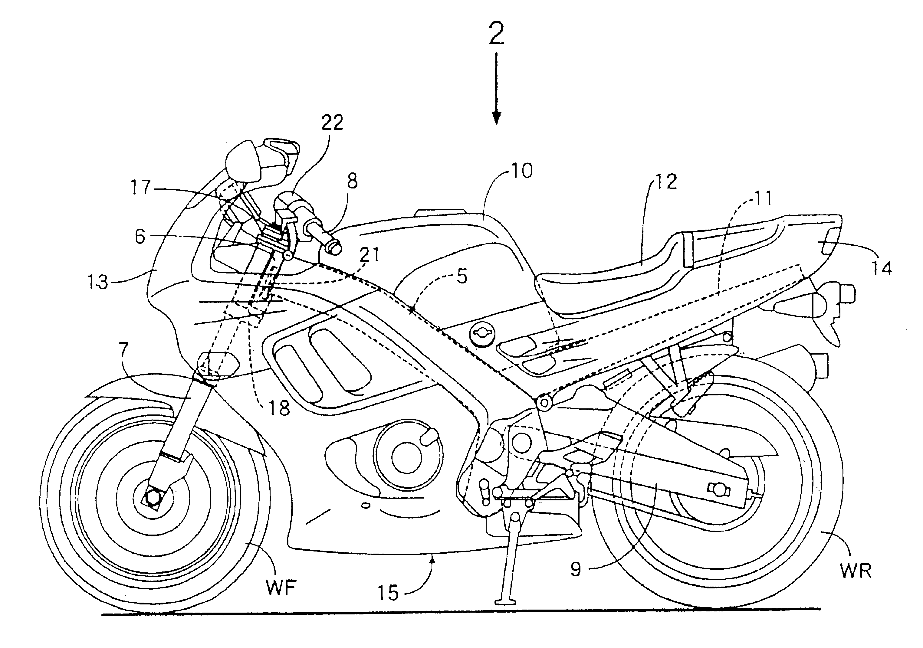
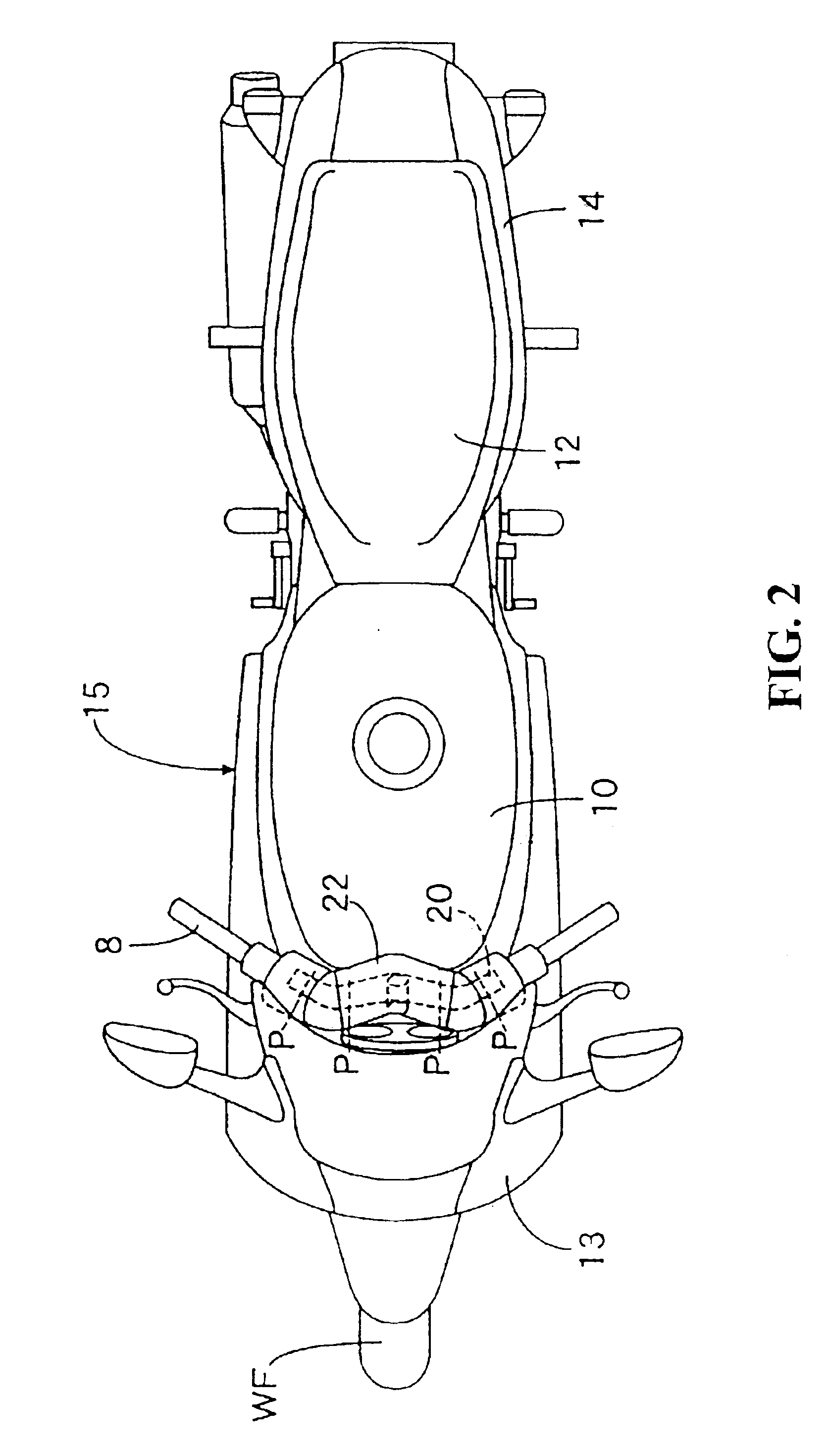
Referring now to FIG. 1 and FIG. 2, a front fork 7 is steerably supported on a head pipe 6 provided at the front end of a vehicle body frame 5 of the motorcycle, and a front wheel WF is rotatably supported at the lower end of the front fork 7. A swing arm 9 is supported at the rear of the vehicle body frame so as to be capable of swinging in the vertical direction. A rear wheel WR is supported at the rear end of the swing arm 9.

A fuel tank 10 is mounted on the front half portion of the vehicle body frame 5, and a tandem seat 12 disposed behind the aforementioned fuel tank 10 and is mounted on a seat rail 11 provided on the rear portion of the vehicle body frame 5.

Most parts of the vehicle body frame 5 are covered by a vehicle body cover 15 made of a synthetic resin and including a front cowl 13 and a rear cowl 14.

In FIG. 3, a pipe stem 16 adapte...


PUM


Abstract

In a compact vehicle including a pipe stem to be inserted into a head pipe wherein the pipe stem is rotatably supported by the head pipe located at the front end on a vehicle body frame. A front fork is provided for rotatably supporting a front wheel being to a top bridge and a bottom bridge secured at the upper and lower ends of the pipe stem. A steering handle is mounted on the top bridge. To simplify the configuration of the airbag and simplifying the connection between the inflator and the airbag is supported on the steering handle and the inflator for supplying gas for inflation and deployment is stored in the pipe stem.

Description

CROSS-REFERENCE TO RELATED APPLICATIONSThe present nonprovisional application claims priority under 35 USC 119 to Japanese Patent Application No. 2002-043807 filed on Feb. 20, 2002 and Japanese Patent Application No. 2002-043806 filed on Feb. 20, 2002 the entire contents thereof are hereby incorporated by reference.BACKGROUND OF THE INVENTION1. Field of the InventionThe present invention relates to a compact vehicle including a pipe stem to inserted into a head pipe which is rotatably supported by the head pipe and located at the front end on a vehicle body frame. A front fork is provided for rotatably supporting a front wheel connected to a top bridge and a bottom bridge secured at the upper and lower ends of the pipe stem and projecting from the upper and lower ends of the aforementioned head pipe. A steering handle is mounted on the aforementioned top bridge. More specifically, the present invention is directed to an improved layout of an airbag apparatus to be mounted on a compa...

Claims


Application Information

Patent Timeline
Patent Type & Authority Patents(United States)
IPC IPC(8): B60R21/16B62J27/00B60R21/26B60R21/00B60R21/20B60R21/2165B60R21/261
CPCB60R21/16B62J27/00B60R21/20B60R2021/0088B60R2021/2612B60R21/2165B62J27/20
Inventor KUROE, TAKESHIIIJIMA, SATOSHITANAKA, AKIKOYAMAMOTO, TAKENORINAMIKI, HIDEO
Owner HONDA MOTOR CO LTD
Learn More