
Gripped bushing system with alternating radial stiffness

a bushing system and radial stiffness technology, applied in the direction of shock absorbers, machine supports, transportation and packaging, etc., can solve the problems of increasing the weight and reducing the service life of the stabilizer bar

Inactive Publication Date: 2005-01-25
AUTOMOTIVE COMPONENTS HOLDINGS
View PDF28 Cites 21 Cited by
  • Summary
  • Abstract
  • Description
  • Claims
  • Application Information

AI Technical Summary

Benefits of technology

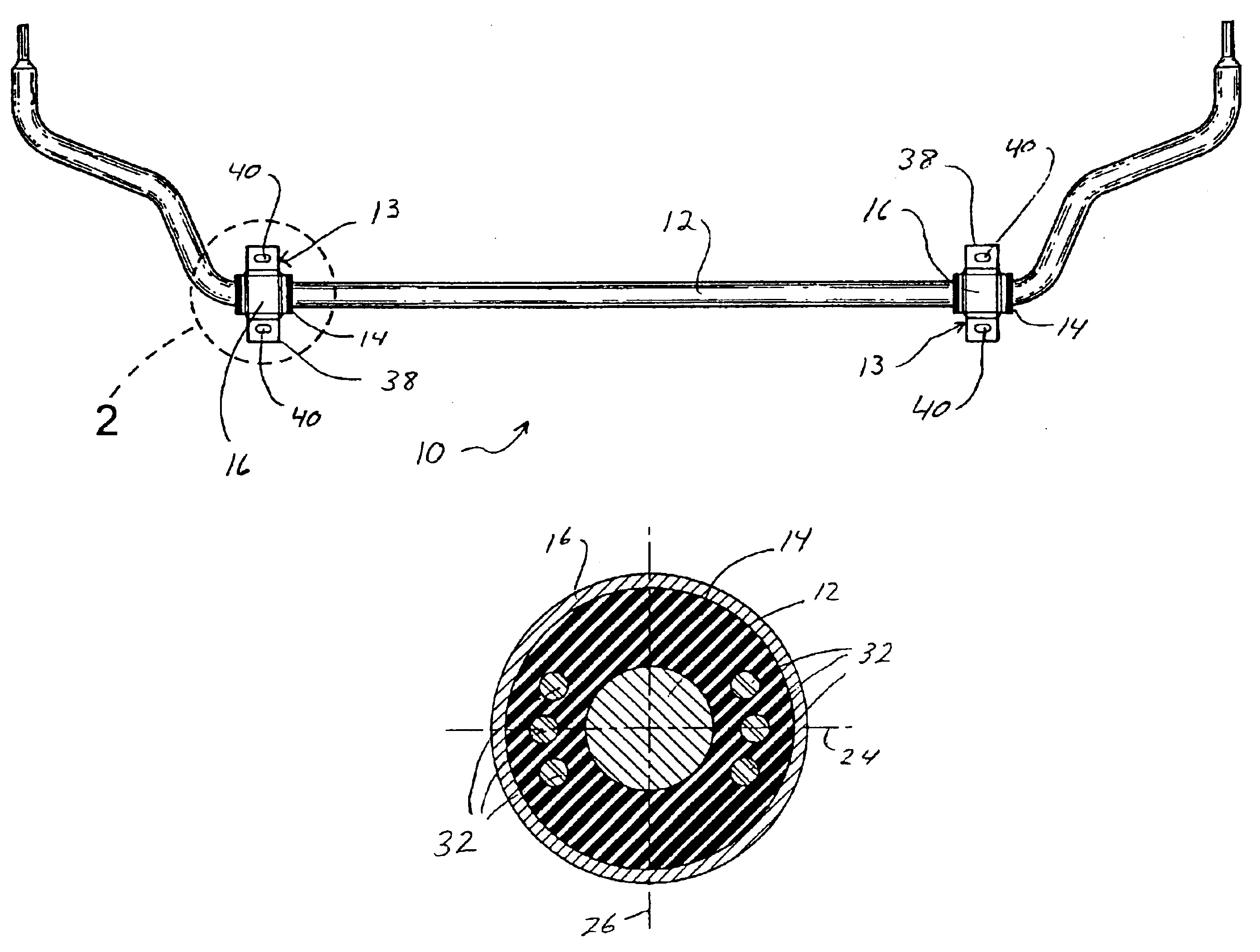
In a first aspect of the present invention the bushing includes voids extending longitudinally through the bushing on opposite sides of the stabilizer bar along one of the first and second radial planes thereby providing a different stiffness between the first and second radial directions.
In another aspect of the present invention, the bushing includes inserts extending longitudinally through the bushing on opposite sides of the stabilizer bar along one of the first and second radial planes thereby providing a different stiffness between the first and second radial planes.
In still another aspect of the present invention the bushing retainer provides a first compressive force along the first radial plane and a second compressive force along the second radial plane thereby providing a different stiffness between the first and second radial planes.
The aspects of the present invention provide a stabilizer bar assembly that provides different stiffness between the first and second planes through the stabilizer bar.

Problems solved by technology

The rubber bushings also dampen the movement of the stabilizer bar.
This makes the stabilizer bar more difficult to manufacture and adds weight to the stabilizer bar.
This, again, adds cost and complexity to the manufacturing process.
Further, after time, the bushings loose some resiliency, thereby causing the feel of the suspension in the vehicle to change.
In order to repair this condition, the bushing would typically have to be replaced, at significant cost.

Method used


Image

  • Gripped bushing system with alternating radial stiffness
  • Gripped bushing system with alternating radial stiffness
  • Gripped bushing system with alternating radial stiffness

Examples


Embodiment Construction

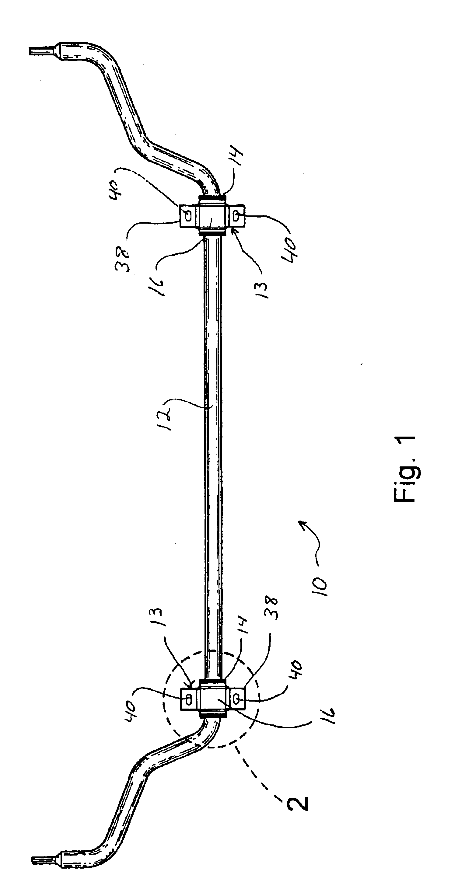
Referring to FIGS. 1-3, a stabilizer bar assembly for an automotive vehicle is shown generally at 10. The stabilizer bar assembly 10 includes a stabilizer bar 12 with at least one bushing assembly 13 mounted thereon. The stabilizer bar 12 is generally made from steel, and can be solid or hollow. It is to be understood, that the stabilizer bar 12 can be made from other suitable materials. The bushing assemblies 13 include a bushing retainer 16 that encompasses a bushing 14 and is in mechanical compressive engagement with the bushing 14 such that the bushing 14 is frictionally engaged with the stabilizer bar 12.

The bushing 14 is made from an elastomeric material, such as rubber, or some other resilient material. The bushing 14 is generally sleeve shaped having an cylindrical outer surface and a round passage extending therethrough defining an inner diameter. Preferably, the inner diameter of the bushing 14 is slightly smaller than an outer diameter of the stabilizer bar 12, however, i...


PUM


Abstract

A stabilizer bar assembly for an automotive vehicle includes a stabilizer bar, a bushing mounted to the stabilizer bar that has a first stiffness in a first radial plane, and a second stiffness in a second radial plane approximately perpendicular to the first radial plane, a bushing retainer in mechanically compressive engagement with the bushing such that the bushing is in frictional engagement with the stabilizer bar, thereby preventing relative movement of the bushing and the stabilizer bar, and a mounting bracket adapted to connect the stabilizer bar to the automotive vehicle.

Description

BACKGROUND OF INVENTION1. Technical Field of the InventionThe present invention generally relates to a stabilizer bar for an automotive vehicle. More specifically, the present invention relates to the mounting of bushing onto a stabilizer bar that produces a frictional engagement between the bushing and the stabilizer bar and provides different radial stiffness across different planes through the stabilizer bar.2. Description of the Prior ArtIn an automotive vehicle, a stabilizer bar helps to keep the vehicle level, particularly when the vehicle is traveling through a curve. The ends of the stabilizer bar are connected to the right and left wheel assemblies of the vehicle. A pair of brackets, positioned between the ends of the stabilizer bar, secure the stabilizer bar to a structural component of the vehicle. Rubber bushings positioned between the stabilizer bar and the brackets provide limited torsional, axial and radial movement of the stabilizer bar relative to the bracket. The r...

Claims


Application Information

Patent Timeline
Patent Type & Authority Patents(United States)
IPC IPC(8): B60G21/055B60G21/00
CPCB60G21/0551B60G2204/41042B60G2204/4104B60G2204/1222
Inventor CAI, HAIMIANLIN, XIGUMMADI, LAKSHMANA
Owner AUTOMOTIVE COMPONENTS HOLDINGS
Learn More