
Data exchange methods for a switch which selectively forms a communication channel between a processing unit and multiple devices

a data exchange and communication channel technology, applied in the field of computers, can solve the problems of reducing system performance, difficult installation, and high cost of scsi components, so as to reduce interrupt handling overhead, avoid overhead associated, and reduce the effect of context switching and other overhead

Inactive Publication Date: 2005-01-18
ORACLE INT CORP
View PDF11 Cites 206 Cited by
  • Summary
  • Abstract
  • Description
  • Claims
  • Application Information

AI Technical Summary

Benefits of technology

One method for exchanging data between the processing unit and multiple devices coupled to the device I / O ports of the switch uses a first PIO technique, wherein several devices may be serviced during execution of a single interrupt service routine. The processing unit issues separate commands to each of the devices (e.g., by repeated application of the general command issue method described above). The processing unit receives an interrupt signal from one of the devices (e.g., via the switch), wherein the interrupt signal conveys a request for service. The processing unit performs an interrupt service routine in response to the interrupt signal. During the interrupt service routine, interrupt signals from all of the devices may be masked. The processing unit reads the contents of an addressable register of the switch during the interrupt service routine, wherein the contents of the register is indicative of interrupt signals from the devices. The register may be, for example, the register of the register set mapped to the address of the ATA standard CYLINDER LOW register. In addition to servicing the device that caused the interrupt, the interrupt service routine may check the register in the switch that indicates the interrupt status for all of the device I / O ports of the switch. If any other interrupts are pending, the interrupt service routine may service those as well before returning. Thus, interrupts from multiple devices attached to different device I / O ports of the switch may be serviced during a single invocation of the interrupt service routine. Servicing multiple IRQs in a single pass through the interrupt service routine may reduce interrupt handling overhead (e.g. by reducing context switching and other overhead associated with going in and out of an interrupt service routine).
Another method for exchanging data between the processing unit and multiple devices coupled to the device I / O ports of the switch uses a second PIO technique, wherein servicing of the devices is batched by masking interrupts from all but a small subset of the devices. The processing unit issues separate commands to each of the devices (e.g., by repeated application of the general command issue method described above). The processing unit masks interrupt signals from all but a select subset of the devices. The processing unit receives an interrupt signal from one of the devices within the select subset of devices (e.g., via the switch), wherein the interrupt signal conveys a request for service. The processing unit performs an interrupt service routine in response to the interrupt signal. During the interrupt service routine, interrupt signals from all of the devices may be masked. The processing unit reads the contents of an interrupt status register of the switch during the interrupt service routine, wherein the contents of the register is indicative of interrupt signals from the devices for each device I / O port of the switch. The register may be, for example, the register of the register set mapped to the address of the ATA standard CYLINDER LOW register, where in the disconnected mode the register services as an interrupt status register. The processing unit may service other devices in addition to the one that caused the interrupt dependent upon the contents of the register. A register may be provided in the switch for masking an interrupt request associated with each device I / O port. This register may be set to mask interrupts from devices expected to be received first after a series of commands has been issued to devices on different ports of the switch. This may increase the likelihood that the processing unit will not be interrupted until multiple ones of the devices are ready for service, since only the subset of devices expected to finish last were left unmasked. Therefore, when the interrupt is serviced, multiple devices may be serviced during the same invocation of the interrupt service routine. The subset size and mask choices in the switch interrupt mask register may allow a trade off to be made between interrupt handling latency and interrupt handling efficiency.
An alternate method for exchanging data between the processing unit and multiple devices coupled to the device I / O ports of the switch uses a third PIO technique, wherein polling is used to service the devices. The processing unit issues separate commands to each of the devices (e.g., by repeated application of the general command issue method described above). The processing unit masks interrupt signals from all of the devices. The processing unit reads the contents of an addressable register of the switch, wherein the contents of the register is indicative of interrupt signals from the devices. The register may be, for example, the register of the register set mapped to the address of the ATA standard CYLINDER LOW register. The processing unit services the devices dependent upon the contents of the register. This technique may allow to avoid overhead associated with interrupt handling. The interrupt mask register in the switch may be used to mask all interrupts from each switch device I / O port from interrupting the processing unit. Device service requests may be handled under control of driver software by example which may periodically or occasionally poll the interrupt status switch and decide the best manner in which to service the devices.

Problems solved by technology

Adding multiple ATA controllers in this manner is typically not only costly, the multiple ATA controllers can also significantly increase communication traffic on the bus to which they are coupled, consequently reducing system performance.
However, SCSI components are typically more expensive than similar ATA components, and can be difficult to install.

Method used


Image

  • Data exchange methods for a switch which selectively forms a communication channel between a processing unit and multiple devices
  • Data exchange methods for a switch which selectively forms a communication channel between a processing unit and multiple devices
  • Data exchange methods for a switch which selectively forms a communication channel between a processing unit and multiple devices

Examples


Embodiment Construction

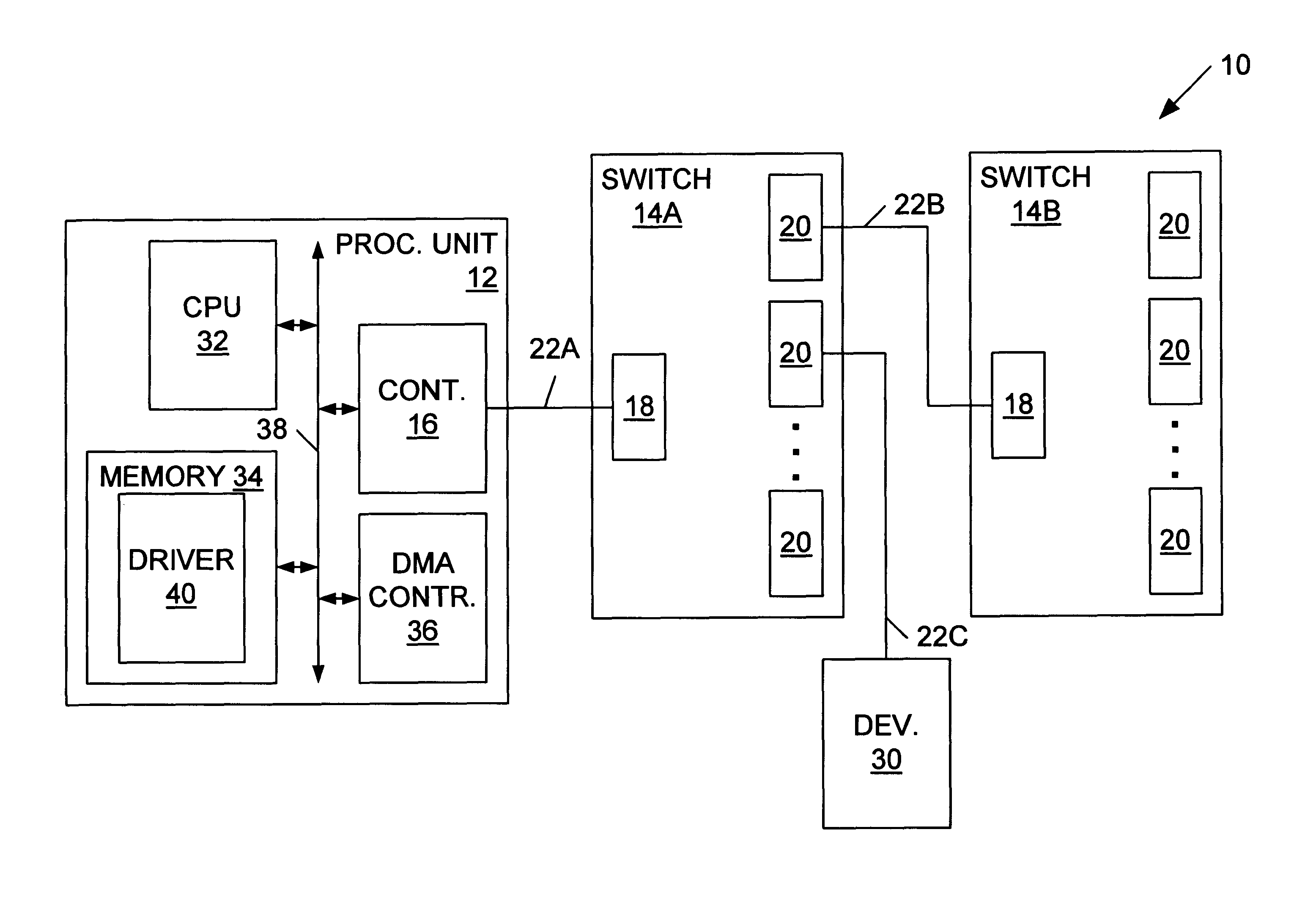
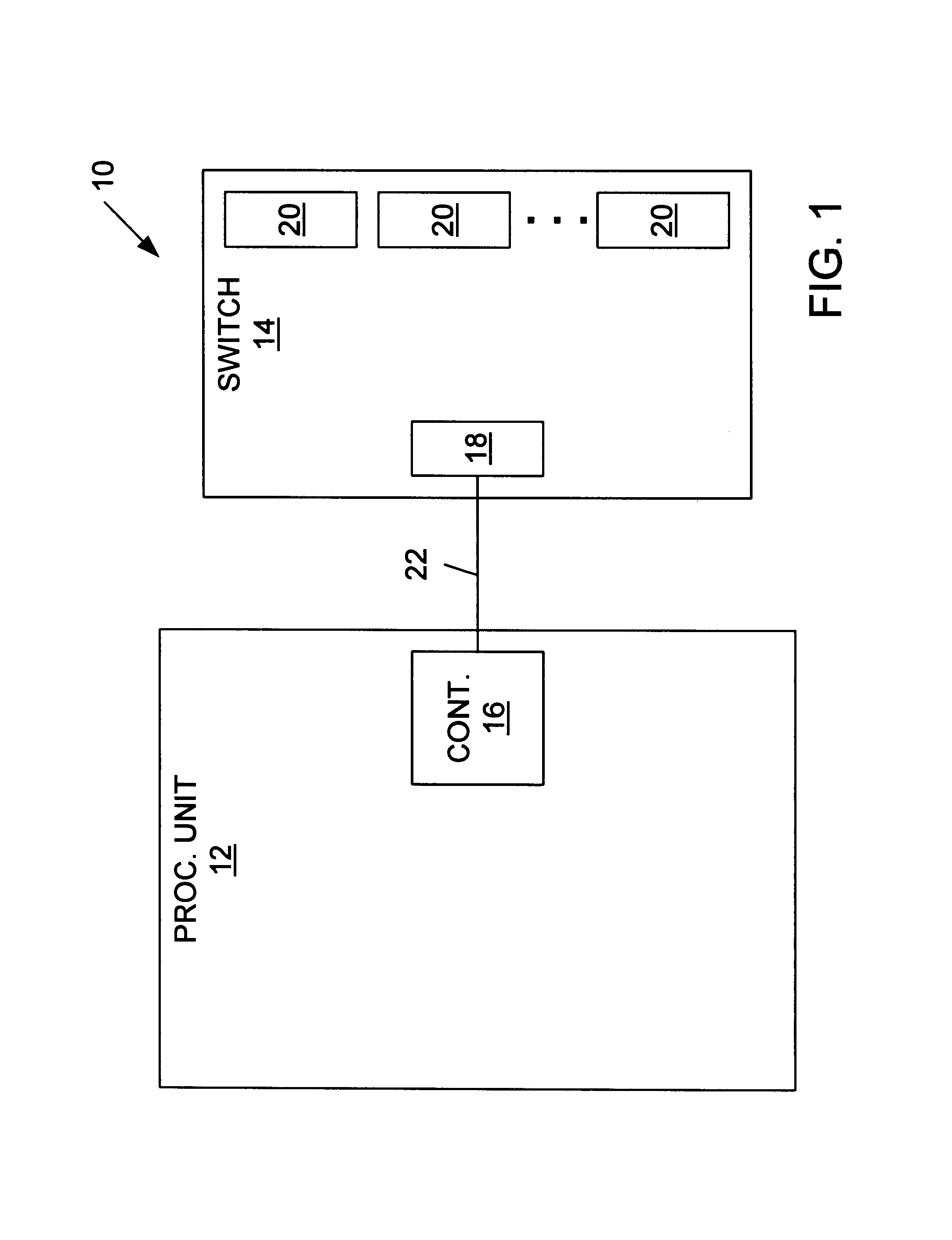
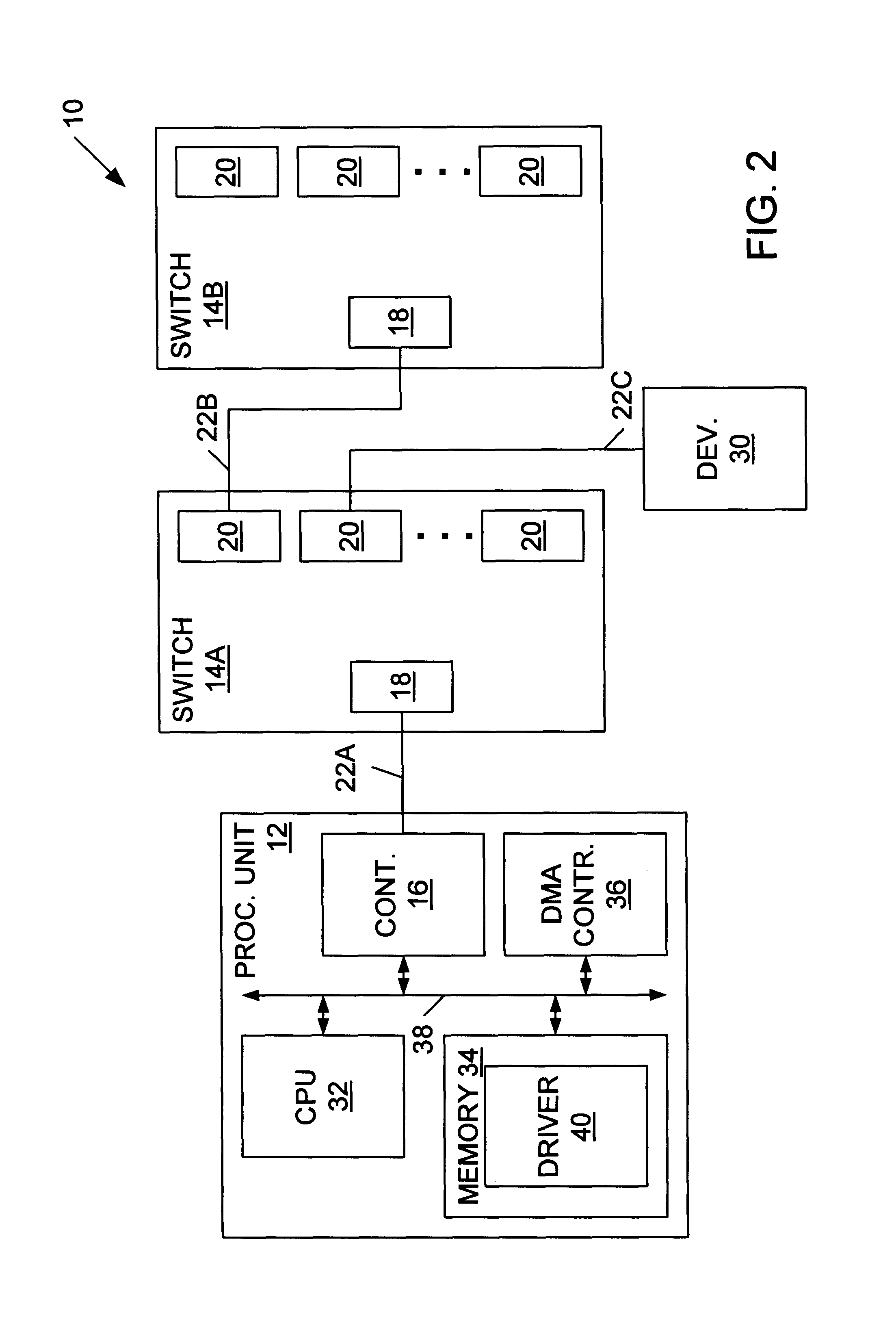
FIG. 1 is a diagram of one embodiment of a computer system 10 including a processing unit 12 coupled to a switch 14 (e.g., an ATA switch). Processing unit 12 includes a controller 16 (e.g., an ATA controller) adapted for coupling to one or more devices (e.g., ATA devices such as disk drives, CD-ROM drives, tape drives, etc.). Switch 14 includes a host input / output (I / O) port 18 and multiple device I / O ports 20. Host I / O port 18 is adapted for coupling to a controller (e.g., an ATA controller), and each device I / O port 22 is adapted for coupling to a device (e.g., an ATA device such as a disk drive, a CD-ROM drive, or a tape drive, or another switch). In FIG. 1, controller 16 is coupled to host port 18 via a bus 22. Controller 16 and bus 22 may conform to AT attachment (ATA) standard ANSI X3.221-1994, or any other ATA standard or variant thereof. As will be described in detail below, switch 14 is configured to form a communication channel (e.g., an ATA communication channel) between ...


PUM


Abstract

A switch is presented including a host input / output (I / O) port adapted for coupling to a controller, multiple device I / O ports each adapted for coupling to at least one device, and logic coupled between the host I / O port and the device I / O ports configured to selectively form a communication channel between the host I / O port and one of the device I / O ports. The switch may operate in a connected mode and a disconnected mode. When in the switch is in the disconnected mode, the logic may not form a communication channel between the host I / O port and any of the device I / O ports. In an ATA embodiment, the switch may comply with an AT attachment (ATA) standard, and thus be an ATA switch. The host I / O port may be adapted for coupling to an ATA controller, the device I / O ports may be adapted for coupling to at least one ATA device, and the logic may selectively form an ATA communication channel between the host I / O port and one of the device I / O ports. Several methods for exchanging data between a processing unit coupled to the host I / O port of the switch and one or more devices coupled to device I / O ports of the switch are described. Several methods for performing direct memory access (DMA) transfers to move data between a memory of the processing unit and one or more of the devices are also described.

Description

BACKGROUND OF THE INVENTION1. Field of the InventionThis invention relates to computer systems, and more particularly to switches for expanding the connection capabilities of computer systems.2. Description of the Related ArtIntelligent / Integrated drive electronics (IDE) is an interface technology for mass storage devices (e.g., disk drives) wherein the controller is integrated into the drive. AT attachment (ATA) is disk drive interface standard which implements IDE. As a result, the two terms and their acronyms are often used interchangeably. Several versions of the ATA standard exist, including the basic ATA standard, Fast ATA, ATA-2, Fast ATA-2, ATA-3, and Ultra ATA. As used herein, the term “AT attachment” and the acronym “ATA” refer to all variants of ATA and other interface standards implementing IDE. The basic ATA standard (ANSI X3.221-1994) supports a single 16-bit parallel data channel which may be shared by two separate devices configured as master and slave. A typical mod...

Claims


Application Information

Patent Timeline
Patent Type & Authority Patents(United States)
IPC IPC(8): G06F3/00G06F3/06
CPCG06F3/0607G06F3/068G06F3/0635
Inventor TALAGALA, NISHA D.LEE, WHAY S.
Owner ORACLE INT CORP
Learn More