
Graphical user input interface for testing performance of a mass storage system

Inactive Publication Date: 2005-01-18
EMC IP HLDG CO LLC
View PDF12 Cites 44 Cited by
  • Summary
  • Abstract
  • Description
  • Claims
  • Application Information

AI Technical Summary

Benefits of technology

Advantageously, therefore, the system easily, and in large part automatically, develops, measures, generates and analyzes statistics describing the dynamic performance of the mass storage system, from the host computers to the disk drive elements, wherein individual operations as well as sequences of operations can easily be set up, with selected initial conditions, and accurately and automatically tested according to desired criteria using graphical user interfaces. The method and apparatus of the invention further advantageously enable the user to easily configure, set, and determine, using a graphical user interface, read / write sequencing and a relative mix of read and write commands, as well as enabling the dynamic performance of the system to be repeatedly enabled and tested for consistency, accuracy, and effectiveness.

Problems solved by technology

A similar distortion, not representative of system performance, can occur when average response time values are determined.
An average response (the average of, for example, a write where cache was available and one where cache was not available) would be misleading and meaningless.
The performance of a large storage system is particularly difficult to measure since more than one of the host computers, which connect to be disk drive controller(s), can operate at the same time, in a serial or in a parallel fashion.
As a result, a plurality of disk drive elements, usually arranged in a disk drive array, operating in either an independent fashion, a RAID configuration, or a mirrored configuration, for example, can have a significant yet undetectable bandwidth or operational problem which cannot be addressed, or discovered, when commands are sent only from a single host computer.
While this system worked well, it had, at the time the application for the system was filed, specific limitations with regard to creating the test configurations and with regard to the flexibility of the analysis and processing once the statistics had been collected.

Method used


Image

  • Graphical user input interface for testing performance of a mass storage system
  • Graphical user input interface for testing performance of a mass storage system
  • Graphical user input interface for testing performance of a mass storage system

Examples


Embodiment Construction

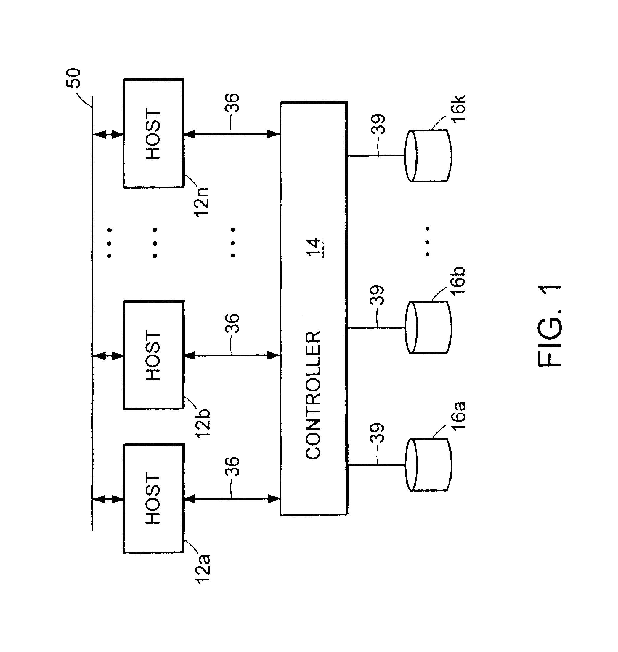
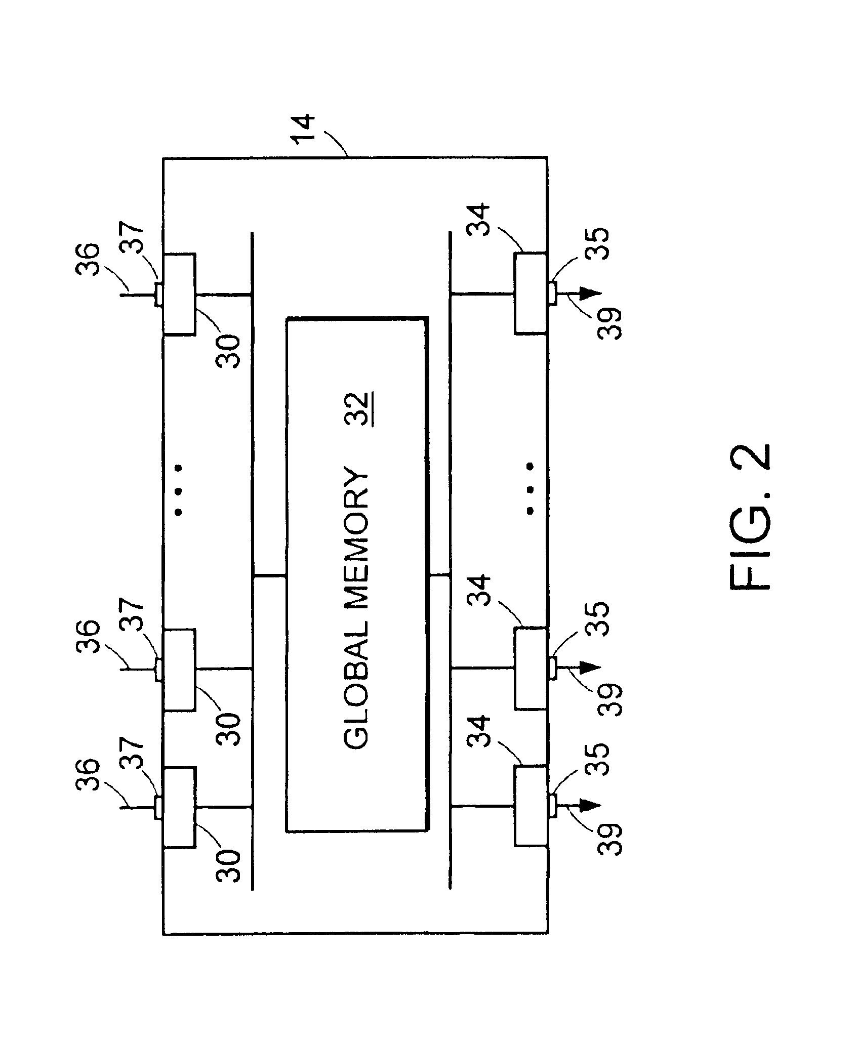
Referring to FIG. 1, the invention relates to a computer system wherein a plurality of host computers or processors 12a, 12b, . . . , 12n, connect to a storage controller system 14, such as the EMC Symmetrix® storage system. The controller acts as an intelligent interface between the host computers and a plurality of mass storage devices, such as, for example, disk drive elements 16a, 16b, . . . , 16k. Data written by the host or read from the disk drive elements passes through the memory controller system which acts as a two way communications path with substantial capabilities. The disk drive elements can have any of, or a combination of, a plurality of configurations. For example, in some systems, the data from a host is uniformly striped across all of the disk storage devices; and in other systems, the data from a host is stored on the disk drives 16 according to a RAID protocol or an n-way mirrored protocol. In yet other embodiments of the invention, all of the data from a part...


PUM


Abstract

A method for measuring mass storage system performance in which the mass storage system has a plurality of disk drive storage elements controlled by a disk drive controller, the controller typically having a cache memory, and the controller receiving commands and data from and returning at least data to a plurality of host computers, provides the flexibility of issuing commands to the controller in a variety of different configurations from a plurality of hosts in a time synchronized and organized fashion. Some significant data reduction techniques control and organize the data for later analysis according to the invention. Time delays and different configurations of both host and storage elements can be effected easily using a novel graphical user interface.

Description

BACKGROUND OF THE INVENTIONThe invention relates generally to tools and systems for measuring the performance of mass storage systems, and more particularly, to methods and apparatus for developing, measuring, analyzing, and displaying the performance statistics of a plurality of disk drive elements controlled through a disk drive controller connected to a plurality of host computers.As the size and complexity of computer systems increase, including the number of host computers and the number of disk drive elements, it becomes increasingly important to measure and understand the functions and parameters which affect the performance of the system. The performance of the system can be typically measured in terms of input / output (I / O) response times, that is, the time it takes for a read or write command to be acted upon, as far as the host computer is concerned, by the disk drive controller system.It is well known, in the field, to measure, usually using a single parameter, the instan...

Claims


Application Information

Patent Timeline
IPC IPC(8): G06F13/00G06F11/32G06F11/34
CPCG06F11/321G06F11/3485G06F11/3414
Inventor LALLY, MAUREEN A.GOGUEN, KENNETH R.LAUTERBACH, PETER C.
Owner EMC IP HLDG CO LLC
Learn More