Eureka AIR delivers breakthrough ideas for toughest innovation challenges, trusted by R&D personnel around the world.

Focus control method and focus controller

a control method and focus controller technology, applied in the direction of instruments, optical discs, disposition/mounting of heads, etc., can solve the problems of difficult to accurately detect the change of the distance between an objective lens and the optical disk in accordance with the change of the reflected light, and achieve the effect of accurate focus control, higher response rate and improved accuracy

Inactive Publication Date: 2005-01-18
SONY CORP
View PDF23 Cites 21 Cited by
  • Summary
  • Abstract
  • Description
  • Claims
  • Application Information

AI Technical Summary

Benefits of technology

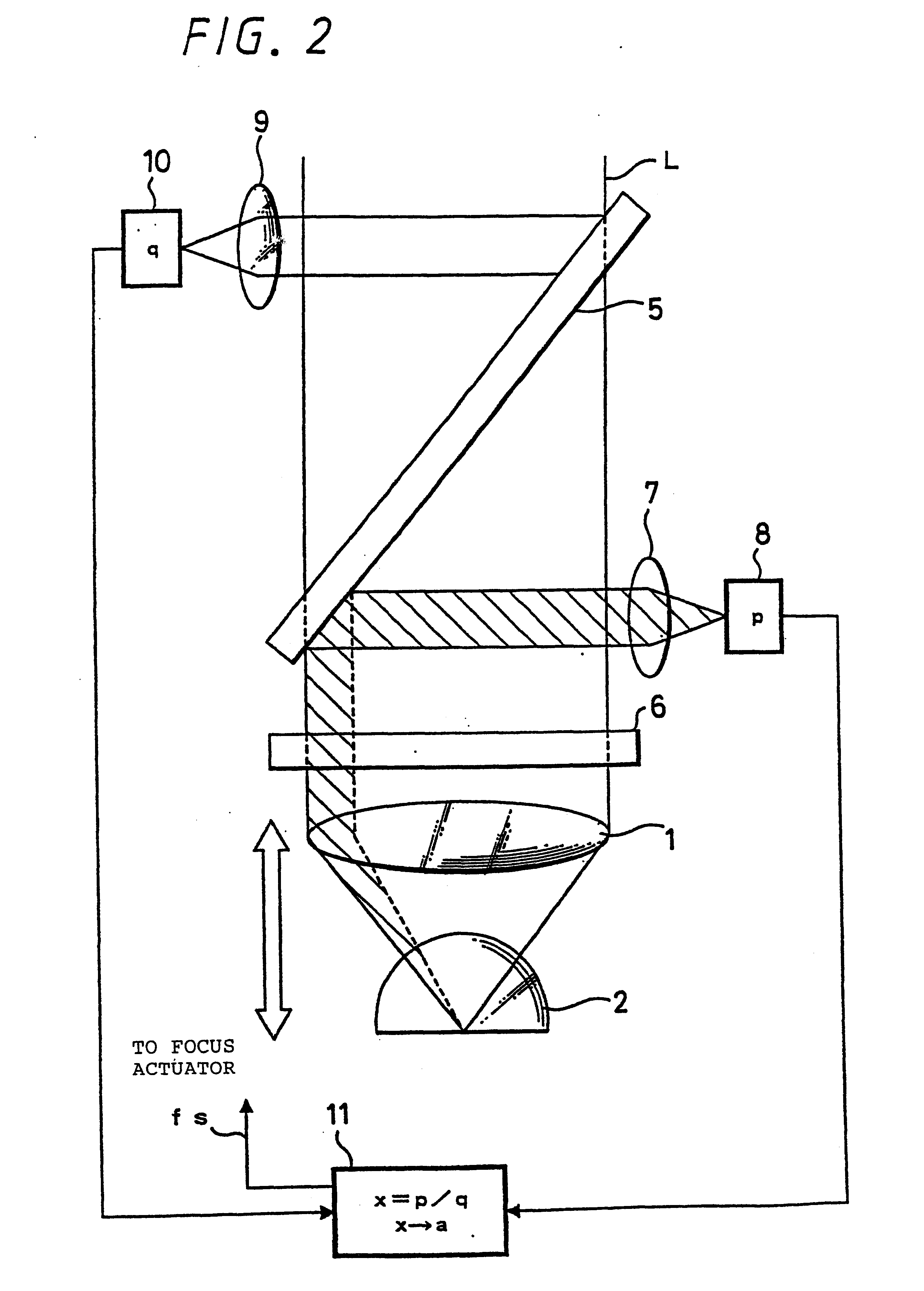
This distance-change detecting method makes it possible to detect the light entering the second optical means from the first optical means at an incidence angle at which a numerical aperture is larger than 1 and reflected from a plane of the second optical means facing the optical recording medium using a solid immersion lens or solid immersion mirror as the second optical means.
Therefore, when applying the method to focus control, it is possible to obtain a large ratio of detection-signal intensity to noise intensity (S / N ratio) in focus control, thus making the control to be performed with higher accuracy.

Problems solved by technology

However, in a very small range such as the near field, even if the distance between the SIL and the optical disk changes, a change of the light reflected from the optical disk is very small.
Thus, it is difficult to accurately detect a change of the distance between an objective lens and the optical disk in accordance with the change of the reflected light.
Therefore, when setting an SIL between an objective lens and an optical disk, it is difficult to perform high-accuracy focus control by the conventional focus control method.
The same problem occurs in a beam irradiator such as an exposure device used for manufacturing a master optical disk for obtaining an information-recording medium such as an optical disk.

Method used


Image

  • Focus control method and focus controller
  • Focus control method and focus controller
  • Focus control method and focus controller

Examples


Embodiment Construction

In the following, an example of applying the present invention to an optical disk drive will be described.

FIG. 1 shows by way of example an optical system provided in an optical pickup of an optical disk drive in order to condense a laser beam to be irradiated to an optical disk and an optical disk set on the optical disk drive.

This optical system comprises an objective lens 1 for condensing a laser beam L and a solid immersion lens (SIL) 2 set between an optical disk 3 and the objective lens 1. The objective lens 1 and the SIL 2 are integrally moved by a focus actuator (not illustrated) in the optical-axis direction of the laser beam L.

The SIL 2 is a lens formed by cutting off a part of a spherical lens in shape and having a refractive index n, which is set so that its spherical surface may be faced toward the objective lens 1 and the plane opposite to the spherical surface may be faced toward the optical disk 3.

The relation between an numerical aperture NA realized by the objectiv...


PUM


Abstract

The present invention aims to perform high-accuracy focus control in an optical disk drive, even if a solid immersion lens (SIL) or a solid immersion mirror (SIM) is set between an objective lens and the optical disk in order to increase a numerical aperture, by accurately detecting a change of the distance between an SIL or SIM and an optical disk.The present invention comprises light detection means (8) for detecting the light incoming to an SIL (2) or an SIM from an objective lens (1) at an incidence angle at which a numerical aperture is larger than 1 and reflected from a plane of the SIL (2) or SIM facing an optical disk, light detection means 10 for detecting the light incoming to the objective lens (1), comparison means (11) for finding a ratio between light amounts of the light detected by light detection means (8) and (10), and control means (11) for controlling operations of a focus actuator in accordance with the ratio.

Description

TECHNICAL FIELDThe present invention relates to, for example, a distance-change detecting method for detecting a change of the distance between an optical system and an object to be irradiated (e.g. optical recording medium) and controlling the distance, a distance-change detector, a focus control method, a focus controller, and totally-reflected-light detecting method, particularly to a method and an apparatus to be preferably applied to an optical system provided with optical means for increasing a numerical aperture such as a solid immersion lens or solid immersion mirror.BACKGROUND ARTInformation is recorded or reproduced in or from an optical disk by narrowing down a laser beam to a very-small spot diameter and making the laser beam irradiate a recording surface of an optical recording medium.To make the laser beam having a certain spot diameter irradiate a recording surface, it is necessary that a distance between an objective lens for condensing the laser beam and an optical ...

Claims


Application Information

Patent Timeline
IPC IPC(8): G11B7/09G11B7/135G11B7/095G11B7/13G11B7/1362G11B7/1372G11B7/1374G11B7/1387G11B7/26
CPCB82Y10/00G11B7/0908G11B7/0917G11B7/0927G11B7/0956G11B7/1374G11B7/1387G11B7/1362G11B2007/13727G11B7/261G11B2007/13725G11B7/1372G11B2220/2537
Inventor SHINGO, IMANISHI
Owner SONY CORP
Why Eureka
Eureka Blog
Learn More