
Torque sensor

a technology of torque sensor and torque detection, which is applied in the field of torque sensor, can solve the problems of reducing affecting the accuracy of torque detection, and increasing the workload of signal processing, so as to achieve high resolution, high accuracy, and low cost

Inactive Publication Date: 2005-01-18
KOYO SEIKO CO LTD
View PDF7 Cites 6 Cited by
  • Summary
  • Abstract
  • Description
  • Claims
  • Application Information

AI Technical Summary

Benefits of technology

[0007]According to the present invention, since the phase change in the first alternating signal corresponds to the change in the rotation angle of the first shaft, and the phase change in the second alternating signal corresponds to the change in the rotation angle of the second shaft, the phase difference between the first alternating signal and the second alternating signal corresponds to the difference between the angles of rotation of the first shaft and the second shaft. The waveform of the phase difference correspondence signal changes in accordance with change in the difference between these angles of rotation, and therefore the phase difference correspondence signal can be used as a signal that corresponds to the torque transmitted by the first and second shafts. In other words, it is possible to determine directly the difference in the rotation angle corresponding to the transmitted torque, without detecting the rotation angle of the first shaft and the rotation angle of the second shaft respectively. Therefore, in order to determine the torque, it is not necessary to directly read in signal output values from detectors by means of a computer, as in the prior art, and hence the workload involved in signal processing can be reduced and non-linear components can be eliminated.
[0008]Furthermore, in the torque sensor according to the present invention, even if the phase change in the first alternating signal does not correspond accurately to the change in the rotation angle of the first shaft due to error, and even if the phase change in the second alternating signal does not correspond accurately to the change in the rotation angle of the second shaft due to error, it is possible to determine a value corresponding to the torque transmitted by the two shafts without being affected by the difference between the respective errors. To be more precise, when there is an error in the phase change in the first alternating signal, this error is represented by a distortion in the waveform of the first alternating signal, and when there is an error in the phase change in the second alternating signal, this error is represented by a distortion in the waveform of the second alternating signal. Therefore, the difference between the first distortion indicator value which changes in accordance with the waveform distortion in the first alternating signal and the second distortion indicator value which changes in accordance with the waveform distortion in the second alternating signal corresponds to the difference between the error in the phase change in the first alternating signal and the error in the phase change in the second alternating signal. Therefore, it is possible to cancel out the effects of the difference between the respective errors by correcting the value corresponding to the transmitted torque, which is determined from the signal corresponding to the difference between the first alternating signal and the second alternating signal, on the basis of a value corresponding to the difference between the first distortion indicator value and the second distortion indicator value.
[0017]According to the present invention, it is possible to provide a torque sensor of high accuracy and high resolution, at low cost.

Problems solved by technology

However, since there are limits on the resolution that can be achieved if a computer directly reads in the signal output value from detectors, such as resolvers, then the resolution of the torque sensor is restricted, and the workload involved in signal processing increases, as the resolution becomes higher.
Moreover, since the output value changes in a non-linear fashion with respect to the rotation angle θ, improvement in the torque detection accuracy is impeded.
Moreover, there are always detection errors in the values of the rotation angles detected by the resolvers or the like, and there are individual differences in the detection errors.
Therefore, if the torque transmitted by the shafts is determined from the detected rotation angle of the first shaft and the detected rotation angle of the second shaft, then the difference between the respective detection errors creates a torque detection error, and hence the torque detection accuracy declines.

Method used


Image

  • Torque sensor
  • Torque sensor
  • Torque sensor

Examples


Embodiment Construction

t logic signal, a second logic signal, and a PWM signal, in a case where torque is transmitted in one direction, in the torque sensor according to the modification of the present invention; and FIG. 9(3) is a diagram showing a first logic signal, a second logic signal, and a PWM signal, in a case where torque is transmitted in the other direction, in the torque sensor according to the modification of the present invention.

[0027]FIG. 10 is a diagram showing the constitution of a phase shift circuit in a torque sensor according to a modification of the present invention.

DESCRIPTION OF THE PREFERRED EMBODIMENTS

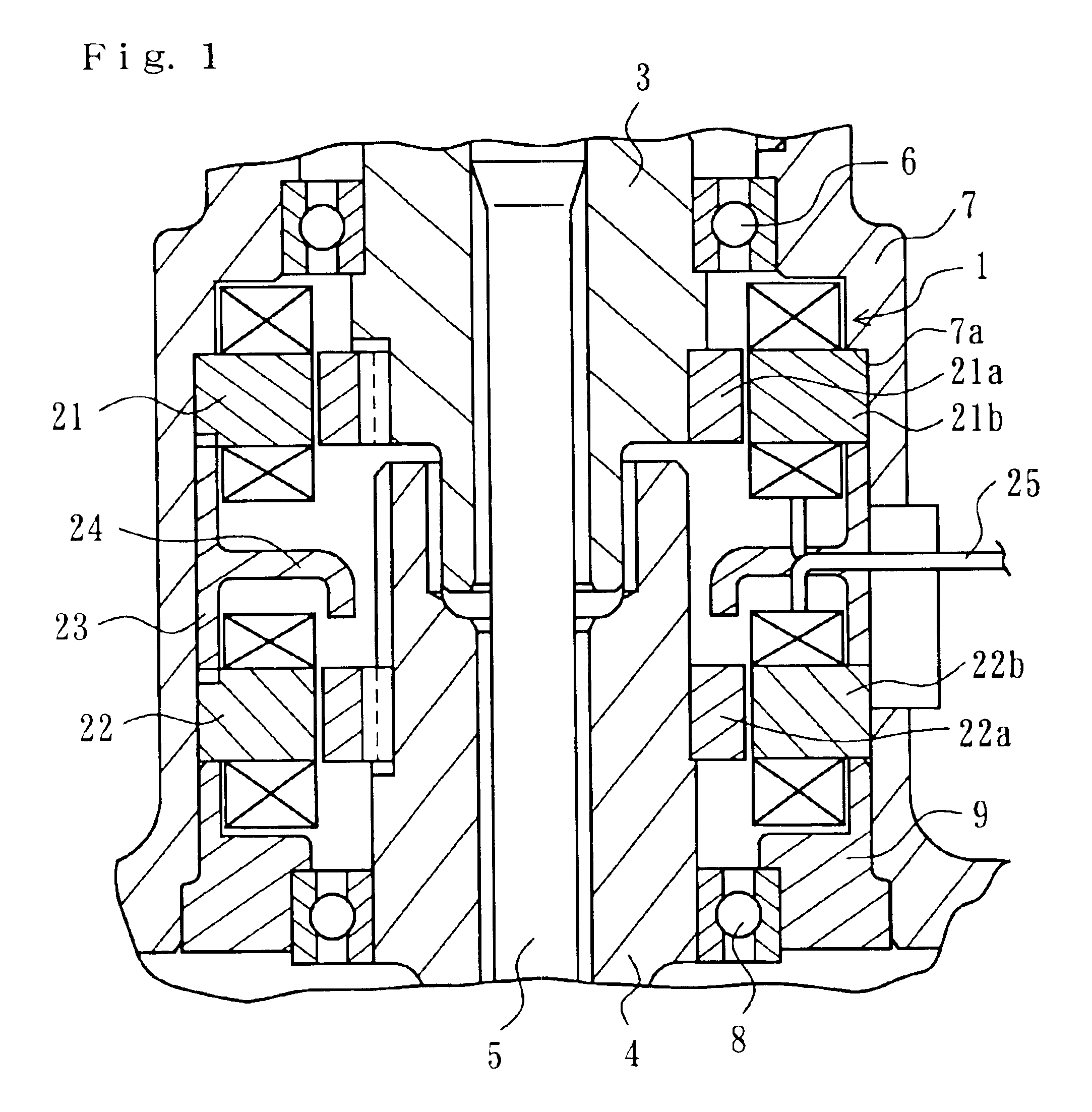
[0028]The torque sensor 1 according to the present embodiment as illustrated in FIG. 1 is used in order to detect the torque transmitted to a steering shaft of an electric power steering apparatus, and it comprises a tubular first shaft 3 and a tubular second shaft 4 constituting the steering shaft. Rotation of a steering wheel (not illustrated) connected to the first shaft 3 is ...


PUM


Abstract

The torque sensor outputs a sinusoidal first alternating signal the phase of which changes in accordance with change in the rotation angle of a first shaft, and a sinusoidal second alternating signal the phase of which changes in accordance with change in the rotation angle of a second shaft capable of performing relative rotation, elastically, with respect to the first shaft. A phase difference correspondence signal the waveform of which changes in accordance with change in the phase difference between the first alternating signal and the second alternating signal is output. A value corresponding to the torque transmitted by the first and second shafts is determined from the phase difference correspondence signal. This value corresponding to the transmitted torque is corrected on the basis of a value corresponding to the difference between a first distortion indicator value which changes in accordance with the waveform distortion in the first alternating signal and a second distortion indicator value which changes in accordance with the waveform distortion in the second alternating signal.

Description

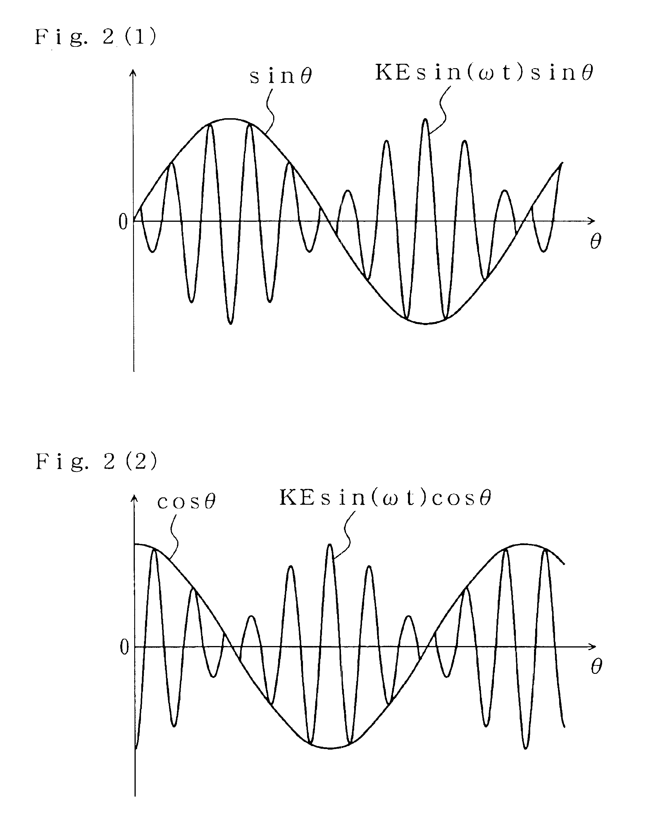
FIELD OF THE INVENTION[0002]The present invention relates to a torque sensor, which is used, for example, to detect the steering torque in an electric power steering apparatus.DESCRIPTION OF THE RELATED ART[0003]A torque sensor is known which comprises a first shaft, a second shaft capable of performing relative rotation, elastically, with respect to the first shaft, a first resolver for detecting the rotation angle of the first shaft and a second resolver for detecting the rotation angle of the second shaft. The torque transmitted by the two shafts is determined by the rotation angle of the first shaft as detected by the first resolver and the rotation angle of the second shaft as detected by the second resolver (Japanese Patent Laid-open No. 2002-350181).[0004]Taking the rotation angle of the shaft as detected by the resolver to be θ, the angular frequency of the excitation signal to be ω, the time to be t, and KE to be a coefficient, then when an excitation signal proportional to...

Claims


Application Information

Patent Timeline
IPC IPC(8): G01L5/22G01L3/12G01L3/10G01L3/02G01L3/14G01D5/245G01D5/12G05B19/19G05B19/29
CPCG01L5/221G01L3/109G01L3/104B62D6/10
Inventor NAGASE, SHIGEKI
Owner KOYO SEIKO CO LTD
Learn More