Illumination system for nonemissive electronic displays

a technology of electronic display and illumination system, which is applied in the field of illumination system for nonemissive electronic display, can solve the problems of reducing the amount of light ultimately reaching the viewer, limited use of nonemissive display backlighting, and limited utility of using nonemissive display backlighting, so as to facilitate substantially uniform illumination of nonemissive electro-optic display medium and dissimilar indices of refraction

Inactive Publication Date: 2005-01-11
E INK CORPORATION
View PDF15 Cites 476 Cited by
  • Summary
  • Abstract
  • Description
  • Claims
  • Application Information

AI Technical Summary

Benefits of technology

It is the object of the invention to facilitate frontlighting of a nonemissive electronic display with minimal undesirable reflection of light away from the display and towards the viewer.
This invention takes advantage of the observation that for nonemissive display technologies, such as encapsulated electrophoretic medium or rotating ball displays, light from nearly all angles of incidence can be efficiently scattered or absorbed resulting. In fact, for such displays, scattering is substantially Lambertian, so the intensity of scattered light reaching a viewer is nearly independent of the angle of incidence, allowing illumination come in from the light transmissive element to the display medium over a wide range of incidence angles.
In some embodiments of this aspect of the invention, the nonemissive display also includes a light source disposed in optical communication with the light transmissive element for generating light for transmission through the light transmissive element. Further, in some variations of these embodiments, the invention features a reflector for directing light from the light source through the light transmissive element. The reflector may have a non-planar surface of predetermined configuration for facilitating substantially uniform illumination of the nonemissive electro-optic display medium. The surface of the reflector may include a plurality of surface elements.
Also, the light transmissive element may include a first component having a first surface; and a second component having a second surface. The first surface mates with the second surface so that the first component and the second component form a lens at the interface therebetween for facilitating substantially uniform illumination of the nonemissive electro-optic display medium. In one variation, the first component and the second component have dissimilar indices of refraction. In other variations, a light conduit, optionally having a lens internally formed therein, is disposed between the light source and the reflector.

Problems solved by technology

Because these displays are nonemissive, their effectiveness is limited to daytime use or to use in lit rooms.
However, the utility of using backlighting with a nonemissive display, such as a microencapsulated electrophoretic display or rotating ball display, is limited because the display medium of such displays is effectively opaque, thus acting as a barrier to light.
In addition, various elements used to increase the uniformity of light passing through the light transmissive element, such as diffusers, decrease the amount of light ultimately reaching the viewer.
Conversely, the design of a frontlighting system for illuminating reflective displays requires a trade-off between achieving uniform illumination of the display and minimizing undesirable reflection of light away from the display and towards the viewer, which lightens the dark state of the display and reduces its perceived contrast.
These systems, however, generally suffer from backscattering because of the addition of two surfaces between the display medium and the viewer, i.e. the front and back surfaces of the front light sheet, as well as because of the micropatterns and other surface elements disposed on one of the surfaces of the front light sheet.

Method used


Image

  • Illumination system for nonemissive electronic displays
  • Illumination system for nonemissive electronic displays
  • Illumination system for nonemissive electronic displays

Examples


Embodiment Construction

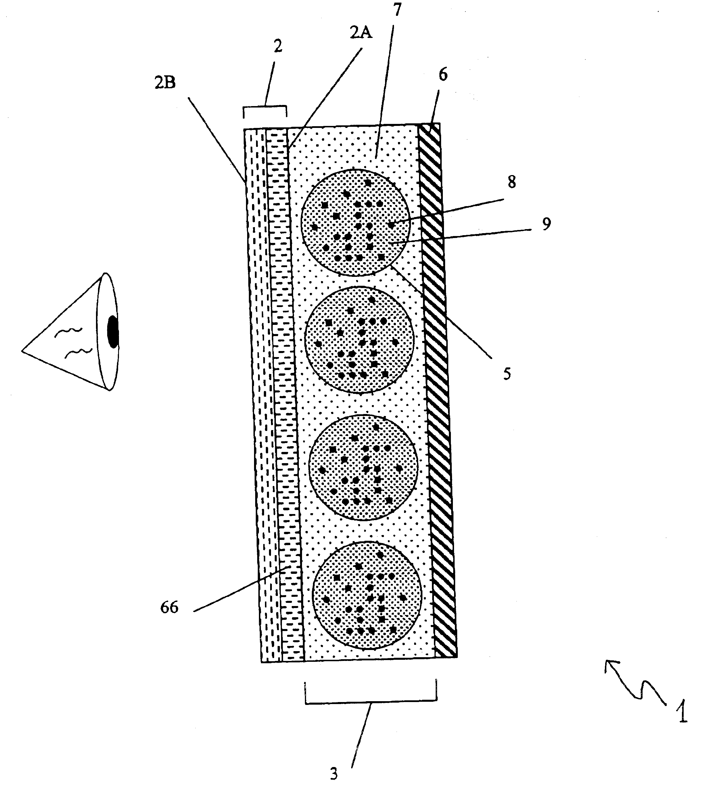
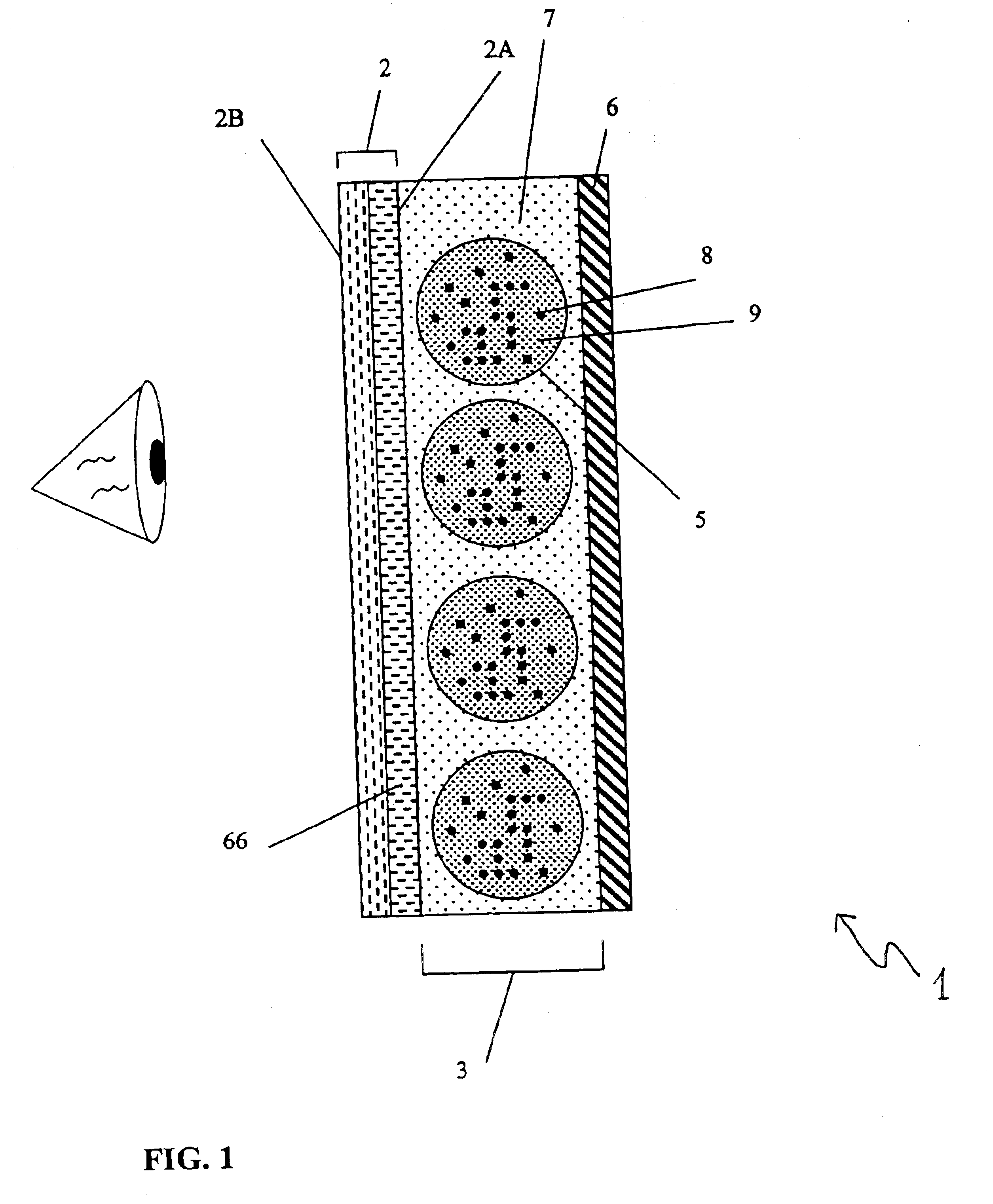
Referring now to FIG. 1, and in brief overview, an illuminated nonemissive electronic display 1 comprises a substrate 2 having a first surface 2a and a second surface 2b. A display medium 3 is disposed adjacent the first surface 2a and includes nonemissive display elements 5 having electrically-responsive optical properties, as discussed in more detail below. A front electrode 66 and a back electrode 6 bound the display medium 3. The back electrode 6 may be patterned electrode which selectively alters the optical properties of the display elements 5 in the display medium 3, generating displays of images and / or text, (moving or still) in response to voltages selectively applied to different areas of the display medium 3.

Throughout the specification, reference will be made to printing or printed. As used throughout the specification, printing is intended to include all forms of printing and coating, including: premetered coatings such as patch die coating, slot or extrusion coating, s...


PUM


Abstract

A frontlighting illumination system for selectively illuminating a nonemissive electronic display includes display elements in communication with at least one light source. The electronic display includes a nonemissive electro-optic medium; and a light transmissive element. Light transmitted through the light transmissive element illuminates the display medium. The propagation of light that is directed through the light transmissive element towards the microencapsulated electrophoretic display medium is substantially undeflected at the interface between the surface of the light transmissive element and the microencapsulated electrophoretic display medium. A reflector is included for directing light from the light source through the light transmissive element.

Description

FIELD OF THE INVENTIONThe present invention relates to a system for illuminating nonemissive electronic displays, and, more specifically, to a system for frontlighting a microencapsulated electrophoretic display.BACKGROUND OF THE INVENTIONThe recent advent of nonemissive electronic display technologies allows the manufacture of inexpensive displays having low power consumption requirements. These displays have uses in a variety of applications such as advertising, information dissemination, education, and entertainment. Because these displays are nonemissive, their effectiveness is limited to daytime use or to use in lit rooms. An illumination system that selectively illuminates the display medium of such a display system is therefore desired.Traditional displays, such as, for example, liquid crystal displays, are typically are illuminated using backlighting. In backlit displays, light from a light source passes through the back of the display via a light transmissive element, such ...

Claims


Application Information

Patent Timeline
IPC IPC(8): G02F1/01G02F1/1335G02F1/13G02F1/167G02F1/13357G02F1/1677
CPCG02F1/1336G02F1/167G02F2001/133616G02F1/1677G02F1/133616
Inventor AMUNDSON, KARL R.
Owner E INK CORPORATION
Why Eureka
Try Eureka