
High water permeability proton exchange membrane

a proton exchange membrane and high water permeability technology, applied in the field of electrochemical cells, can solve the problems of reactant fluid cross-over, local over heating, and rate drop, and achieve the effect of high water permeability and enhanced water permeability

Inactive Publication Date: 2005-01-11
AUDI AG
View PDF4 Cites 25 Cited by
  • Summary
  • Abstract
  • Description
  • Claims
  • Application Information

AI Technical Summary

Benefits of technology

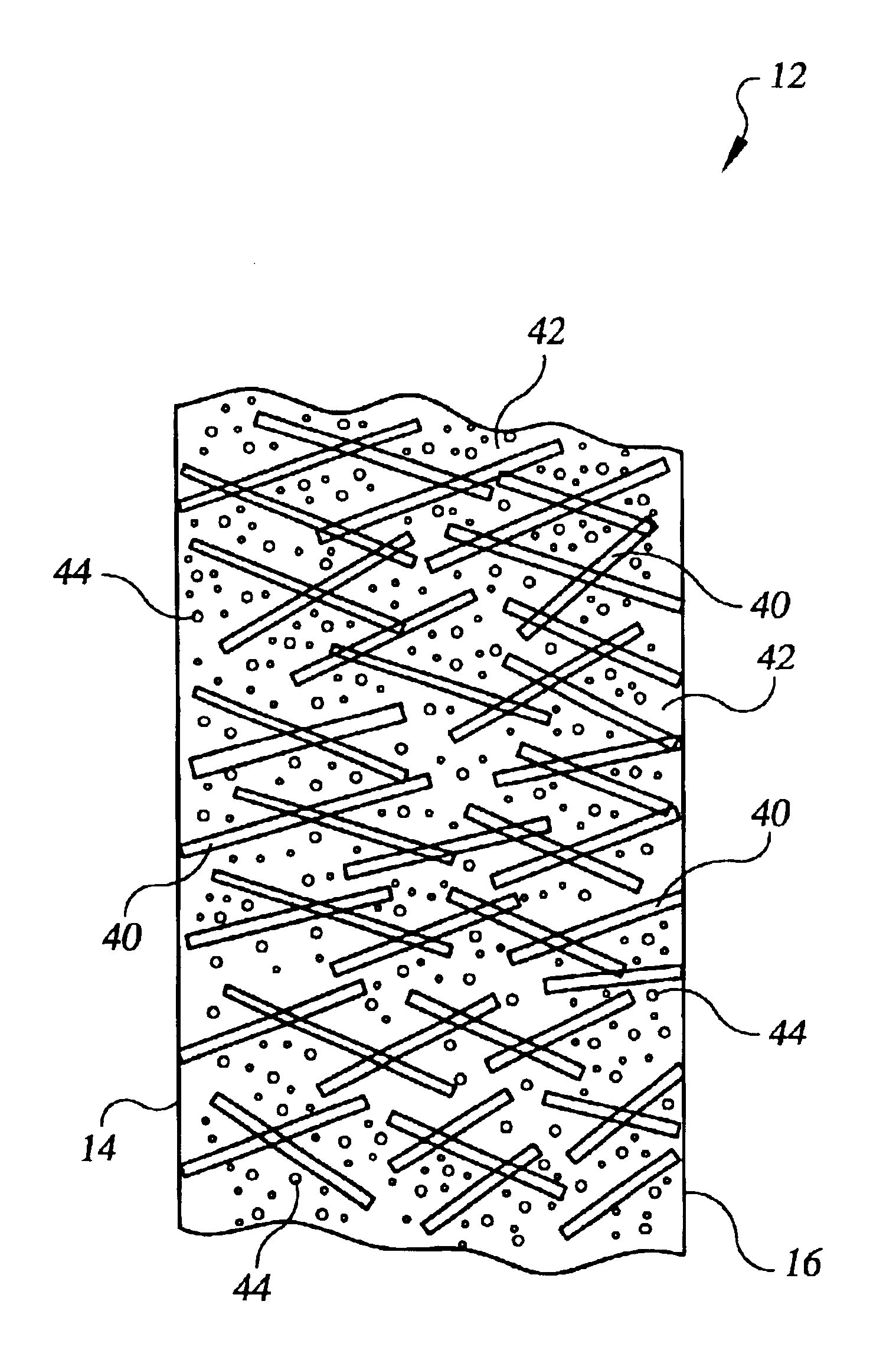
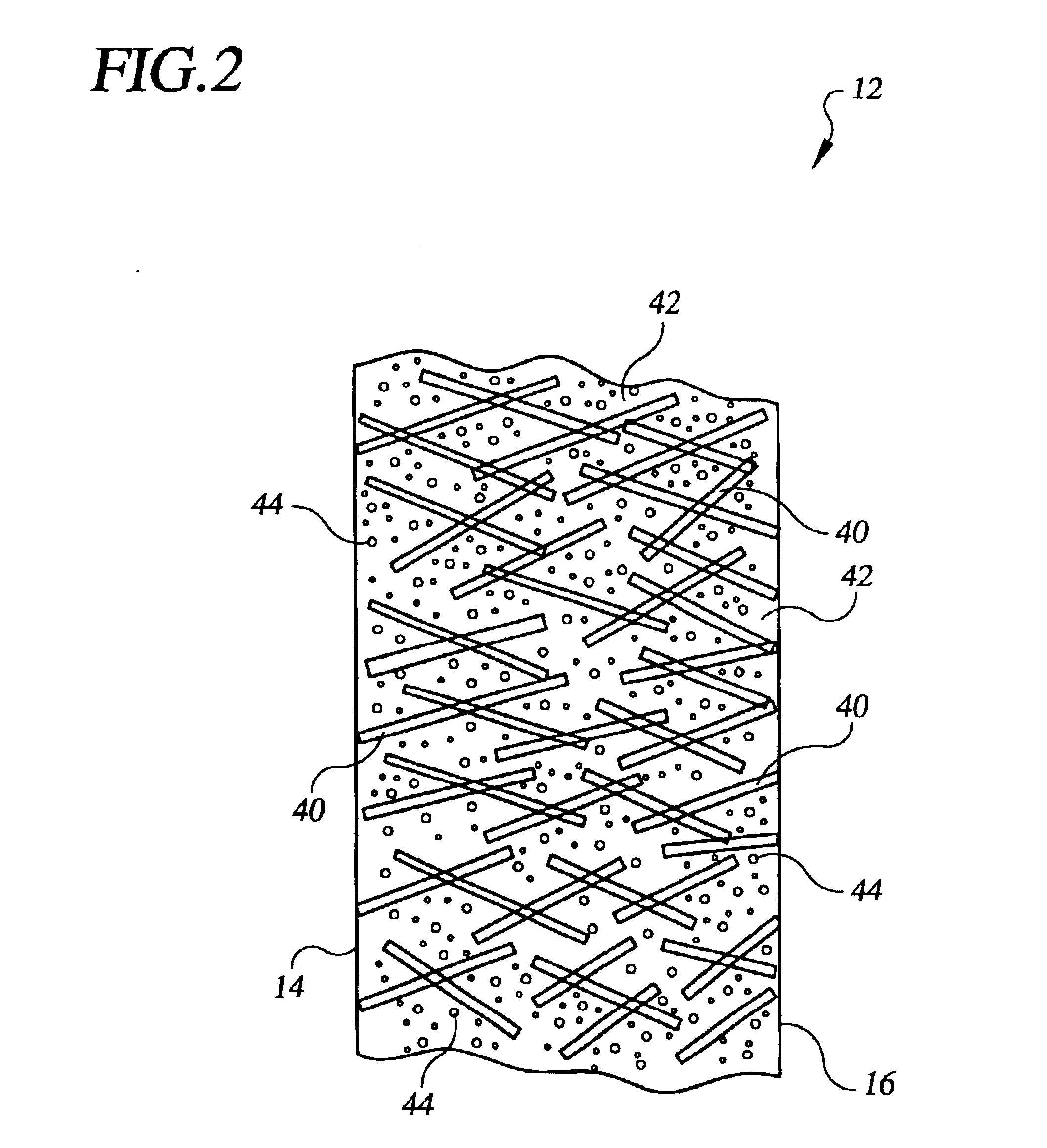
The present invention provides a high water permeability proton exchange membrane for use in electrochemical cells that overcomes deficiencies of the prior art. The membrane has a unique structure that enhances water permeability throughout catalyst surfaces of the membrane. The membrane consists of a structural insulating phase, a hydrated nanoporous ionomer phase, and a microporous water-filled phase. The membrane has a high water permeability, making it suitable for use in fuel cells and electrolysis cells. The method of making the membrane involves positioning the materials and then filling the void volume with the ionomer phase material. The resulting membrane is about 10-25 microns thick and has a unique structure that enhances water permeability.

Problems solved by technology

If insufficient water is returned to the anode electrode, adjacent portions of the PEM electrolyte dry out thereby decreasing a rate at which hydrogen ions may be transferred through the PEM and also resulting in cross-over of the reactant fluid leading to local over heating.
Dry-out of the PEM electrolyte also results in degradation of the PEM electrolyte, as is known.
Similarly if insufficient product water is removed from the cathode electrode, the cathode may become flooded effectively limiting oxidant supply to the cathode and hence decreasing current flow.
While ultra-thin PEM electrolytes have enhanced water permeability, nonetheless, significant electrochemical cell performance limits result from restricted PEM water permeability.
Additionally, fuel cell durability and performance is known to be degraded as a result of catalyst flooding with product water.

Method used


Image

  • High water permeability proton exchange membrane
  • High water permeability proton exchange membrane
  • High water permeability proton exchange membrane

Examples


Embodiment Construction

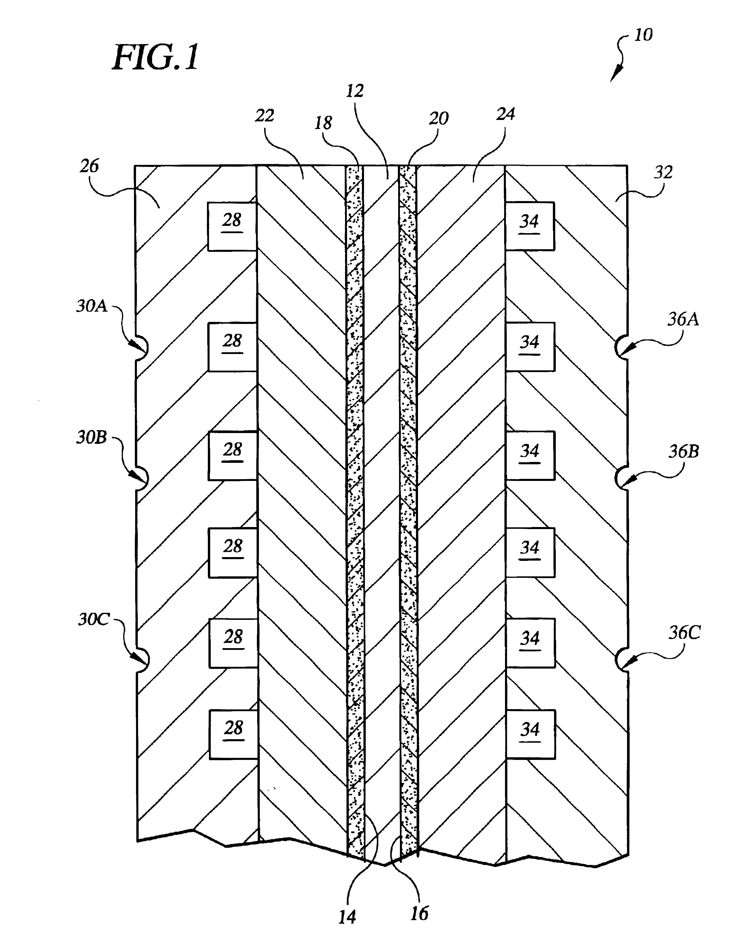
Referring to the drawings in detail, an electrochemical cell, such as a fuel cell 10 is shown schematically as a working environment for a high water permeability proton exchange membrane (“PEM”) 12. The high water permeability PEM 12 is shown having a first catalyst surface 14 and an opposed second catalyst surface 16. An anode catalyst 18 and a cathode catalyst 20 are supported adjacent to the opposed first and second catalyst surfaces 14, 16 of the PEM 12. A porous anode substrate 22 is secured adjacent to the anode catalyst 18, and a porous cathode substrate 24 is secured adjacent to the cathode catalyst 20. An anode water transport plate 26 is secured adjacent to the anode substrate 22, and the anode water transport plate 26 defines a reducing fluid distribution network 28 and a plurality of anode side water channels 30A, 30B, 30C. A cathode water transport plate 32 is secured adjacent to the cathode substrate 24, and the cathode water transport plate 32 defines a process oxida...


PUM

PropertyMeasurementUnit
volume percentaaaaaaaaaa
diameteraaaaaaaaaa

Abstract

A high water permeability proton exchange membrane (12) is disclosed for use in an electrochemical cell, such as a fuel cell (10) or an electrolysis cell. The membrane (12) includes: a. between about 20 volume percent (“vol. %”) and about 40 vol. % of a structural insulating phase (40); between about 50 vol. % and about 70 vol. % of a hydrated nanoporous ionomer phase (42); and, about 10 vol. % of a microporous water-filled phase (44). The structural insulating material (40) defines an overall membrane volume, and the ionomer phase (42) fills all but 10% of the overall volume so that the microporous water-filled phase (44) is defined within the ionomer phase (42) and consists of open pores having a diameter of between 0.3 microns and 1.0 microns. Water transport is enhanced between opposed catalytic surfaces (14), (16) of the membrane (12).

Description

TECHNICAL FIELDThe present invention relates to electrochemical cells such as stacks of electrochemical cells used in fuel or electrolysis cells, and especially relates to a high water permeability proton exchange membrane for use as an electrolyte in such an electrochemical cell.BACKGROUND ARTElectrochemical cells are commonly used in a fuel cell configuration to produce electrical energy from reducing and oxidant fluid streams, or in an electrolysis cell configuration to produce product gases from a supply fluid such as producing hydrogen and oxygen gas from water, as is well known. Typical applications employ a plurality of planar cells arranged in a stack surrounded by an electrically insulating frame that defines manifolds for directing flow of reactant and product fluids. Electrochemical cells typically include an anode electrode and a cathode electrode separated by an electrolyte. In both fuel cells and electrolysis cells, operating efficiencies are enhanced by increased wate...

Claims


Application Information

Patent Timeline
Patent Type & Authority Patents(United States)
IPC IPC(8): C08J5/20C08J5/22H01M8/10B01D69/10H01MH01M8/02H01M8/04
CPCB01D69/10C08J5/2275H01M8/1039H01M8/106H01M8/1062H01M8/1023H01M8/0291H01M8/04291Y02E60/521H01M2008/1095H01M8/0289Y02E60/50B01D69/106
Inventor BREAULT, RICHARD D.
Owner AUDI AG
Learn More