
Consolidated body fluid testing device and method

a body fluid and testing device technology, applied in the field of methods and devices for testing analysis fluids, can solve the problems of limited market size, limited features for consumers and users, and limited current system for glucose measurement, so as to facilitate ease and speed of performance, enhance the flow of blood, and reduce product clutter

Inactive Publication Date: 2005-01-11
KLOEPFER DR HANS
View PDF15 Cites 454 Cited by
  • Summary
  • Abstract
  • Description
  • Claims
  • Application Information

AI Technical Summary

Benefits of technology

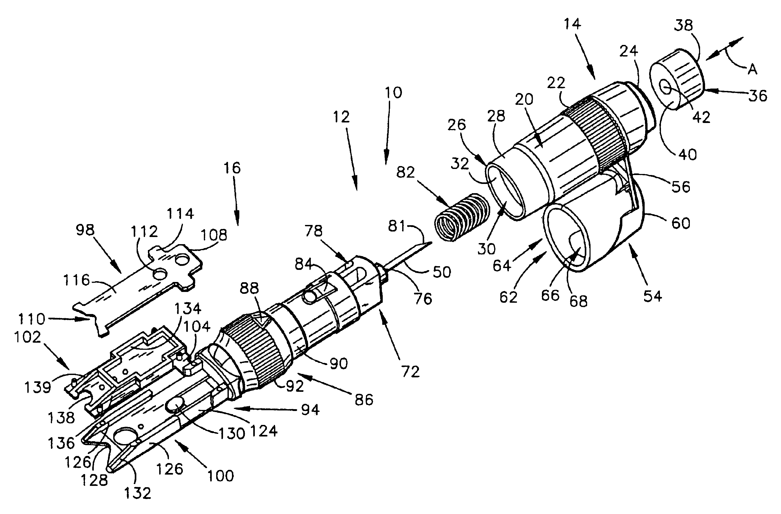
"The present invention is a consolidated body fluid testing device that includes a testing apparatus and a disposable testing device. The disposable testing device includes a tissue penetrator, a test strip holder, and a test strip. The device also includes a cleansing member and a pressure inducing member. The consolidated testing device reduces the number of separate items that the user must handle, makes testing faster, and safer for diabetics. The device also includes a removable lancet cap for easy replacement and a living hinge snap cap for sample enlargement. The ultra-miniaturization of sample size is enabled by a thin film, capillary-augmented sample acquisition process."

Problems solved by technology

From a provider perspective, the main shortfall is that current systems are generally limited to the measurement of glucose.
From a user point of view, there are still limitations in those features that consumers and users believe to be important, such as (1) minimal invasiveness; (2) speed of analysis and (3) ease of performance and minimal complexity (inconvenience) from primary and auxiliary product mixes.
Non-invasive and minimally invasive technologies (such as the one of the instant invention) have been under active development for years, but made it to market only on a very limited scale due to technical difficulties.
However, since the two can usually not be completely spatially separated, pure signals are by definition unobtainable.
Unfortunately, the important feature of visual backup is realized only in a minority of present systems.
This limitation resides in the method by which cellular component of blood is separated from plasma.
Cells were then manually removed from the site of blood application by either washing or wiping them away, potentially giving rise to significant operator-induced errors.
The dream goal for the SMBG market of a completely non-invasive glucose monitoring technology, although pursued for over a decade, has so far proven elusive, despite perennial promises from companies in the industry.
These failures have led to predictions that completely non-invasive optical technology (infrared or other) may not make it to market in any significant way, for both cost and technical reasons.
It is also argued that this lack of success was predictable from early theoretical considerations of signal engineering.
Clark error grid presentation shows performance that is not acceptable for home glucose meters.”
Reported problems with IF sampling are variations in skin thickness and permeability, changes in blood / IF equilibration, sweating, signal instability and skin irritation.
In this environment a market conversion from established and affordable invasive whole blood technology to unproven and costly non-invasive systems appears unlikely.
However, it is expected that the market will migrate to invasive systems which minimize invasiveness and its associated pain.
It is a perceived burden by users, and a deterrent for many diabetics to perform SMBG at all.

Method used


Image

  • Consolidated body fluid testing device and method
  • Consolidated body fluid testing device and method
  • Consolidated body fluid testing device and method

Examples


Embodiment Construction

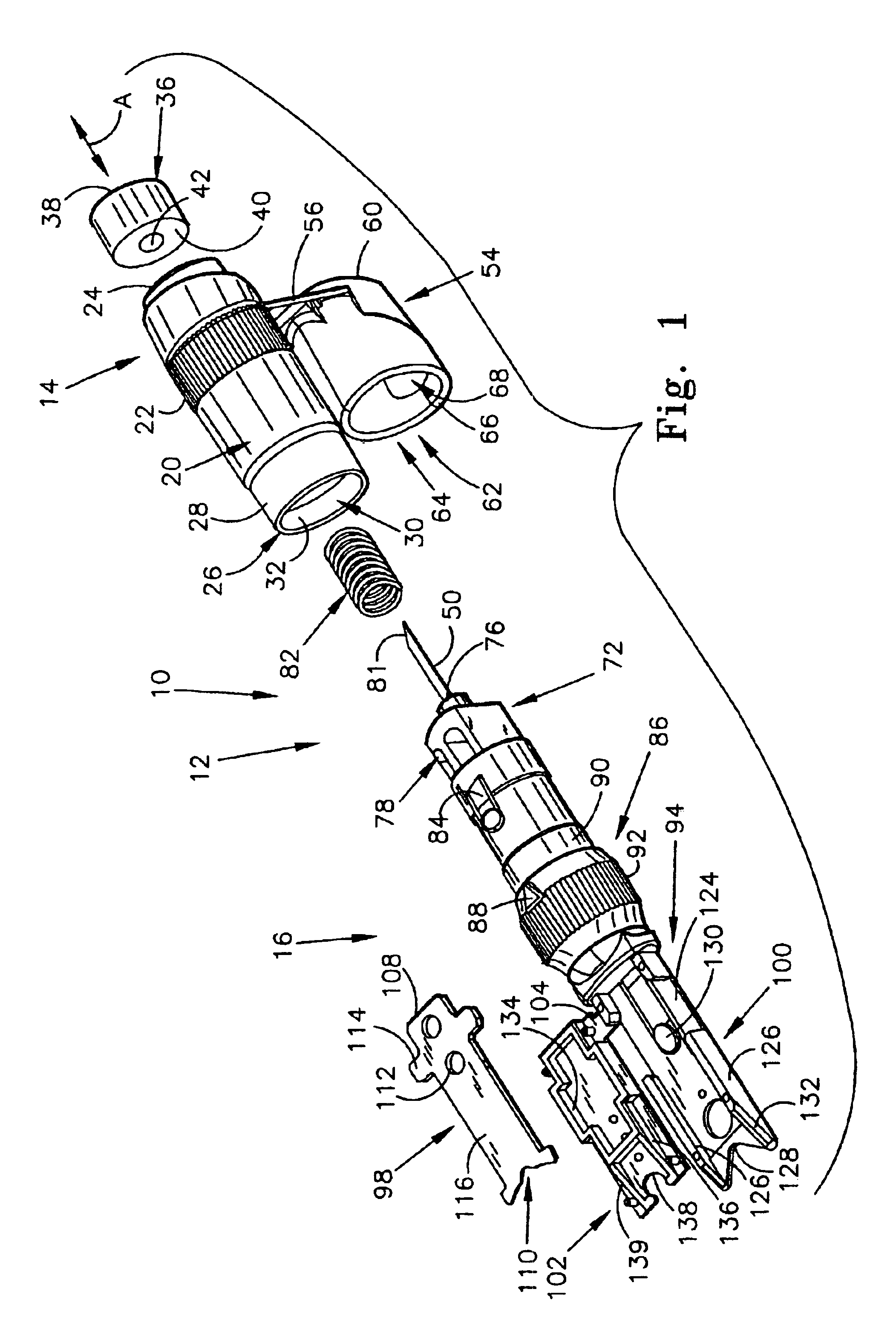
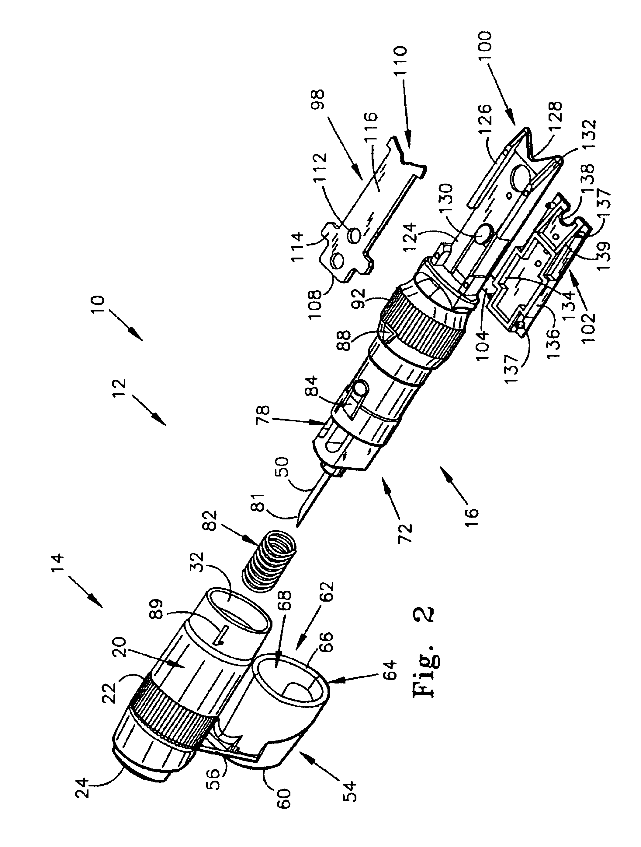
54]FIG. 6 is another perspective view of the first alternate embodiment of the present invention;

[0055]FIG. 7a is a schematic flowchart illustrating the steps necessary to perform a blood test using the prior art;

[0056]FIG. 7b is a flowchart illustrating the steps necessary to perform a blood test using the testing device of the present invention;

[0057]FIG. 8 is a bottom view of the first alternate embodiment of the present invention;

[0058]FIG. 9 is a top view of the first alternate embodiment of the present invention;

[0059]FIG. 10 is a side view of the first alternate embodiment of the present invention;

[0060]FIG. 11 is a perspective view, illustrating the pressure cap of the present invention;

[0061]FIG. 12 is a perspective view, wherein the pressure cap in its open position, and the cleansing swab is exposed;

[0062]FIG. 13 is a perspective view, similar to FIG. 12, but with the cleansing swab removed to illustrate the cleansing swab receiving chamber;

[0063]FIG. 14 is a top view the...


PUM


Abstract

A body fluid testing device includes a body member and a tissue penetrator carried by the body member. A test strip holder is carried by the body member, and a test strip is carried by the test strip holder. The test strip is capable of receiving a body fluid thereon and processing the body fluid into a form suitable for yielding test results relating to the content of the body fluid.

Description

I. CLAIM OF PRIORITY[0002]The instant application claims priority to Kloepfer, Kloepfer and Roach, U.S. Provisional Patent Application No. 60 / 340,442 filed Dec. 7, 2001.IA. GOVERNMENT INTEREST STATEMENT[0003]This invention was made with Government support under grant number R44 DK59219 from the National Institutes of Health. The government has certain rights to this invention.II. TECHNICAL FIELD OF THE INVENTION[0004]The present invention relates to methods and devices for testing analysis fluids, and more particularly to a consolidated testing apparatus for use in performing analyses of one or more components of a fluid. Significant contemplated applications of the invention are in the biological sciences, especially diagnostic medicine. In this field, analysis fluids would primarily be bodily fluids, notably whole blood.III. BACKGROUND OF THE INVENTION[0005]A. Overview of Disease Conditions Warranting a Need for the Present Invention.[0006]Diabetes has been referred to as the “und...

Claims


Application Information

Patent Timeline
Patent Type & Authority Patents(United States)
IPC IPC(8): A61B5/15
CPCA61B5/1411A61B5/15142A61B5/151A61B2562/0295A61B5/150022A61B5/150068A61B5/150259A61B5/150358A61B5/150412A61B5/150503A61B5/150824A61B5/15113A61B5/15117A61B5/1519A61B5/150183
Inventor KLOEPFER, HANS G.HAFELLNER, REINHARDROACH, CHARLES W.THOMECZEK, CHARLES
Owner KLOEPFER DR HANS
Learn More