Electrical connector with lock and shield pieces in middle plane

a technology of shield pieces and electric connectors, which is applied in the direction of electrical equipment, current collectors, coupling device connections, etc., can solve the problems of insufficient space for absorption of inability to provide locking arms and shield pieces on the lower surface of metal cases together with fixing legs, and inability to provide a flat plane with sufficient space for absorption, so as to minimize the influence of the thickness of the bent portion on the height of the apparatus , smooth guide the ma

Inactive Publication Date: 2005-01-11
HIROSE ELECTRIC GROUP
View PDF8 Cites 34 Cited by
  • Summary
  • Abstract
  • Description
  • Claims
  • Application Information

AI Technical Summary

Benefits of technology

Accordingly, it is an object of this invention to provide an electrical connector with a rectangular case, which can be used while seeing the display and easily assembled automatically.
According to such an electrical connector, when the display section of an electronic apparatus, such as a portable telephone, faces upward, electronic components, such as the electrical connector are positioned under a circuit board. When mounted on the circuit board, the electronic components are absorbed and transported by an automatic machine and soldered onto the circuit board at a predetermined position under the condition that the circuit board is turned upside down. The electrical connector according to the present invention is easily absorbed by the machine because the upper surface of the rectangular case is made flat.
The substantially rectangular case can have a lower opening in at least part of the lower surface to accommodate a bottom section of the housing. The housing is made of an insulating material so that even if a circuit section is provided at a corresponding position of the circuit board, there is no risk that the circuit section is short-circuited by the close approach or contact of the bottom section of the housing to or with the circuit section. Thus, the circuit section is arranged at the corresponding position effectively.
The substantially rectangular case has a projection portion extending forwardly from part of an edge of the front opening thereof. If the projection portion is inserted into a window of a front panel of the apparatus, the positioning of the connector is easily performed with respect to the window.
If a lower side of the bent portion of the resilient lock piece is positioned lower than that of a plane where the housing is fixed to the circuit board, part of the thickness of the bent portion is within the thickness of the circuit board so that the influence of the thickness of the bent portion on the height of apparatus is minimized.

Problems solved by technology

Even if the receptacle connector is used upside down to solve the problem, the locking arm and shield piece cannot obtain a sufficient amount of displacement because they are provided by cutting upward the upper surface of the metal case.
Also, it is difficult to provide the locking arm and shield piece on the lower surface of the metal case together with the fixing legs because the fixing legs are provided there by cutting downward the metal case.
However, as described above, the upper surface of the metal case of the receptacle connector is provided with the locking arm so that there is no flat plane having a sufficient space for the absorption.

Method used


Image

  • Electrical connector with lock and shield pieces in middle plane
  • Electrical connector with lock and shield pieces in middle plane
  • Electrical connector with lock and shield pieces in middle plane

Examples


Embodiment Construction

Embodiments of the present invention will now be described with reference to the accompanying drawings.

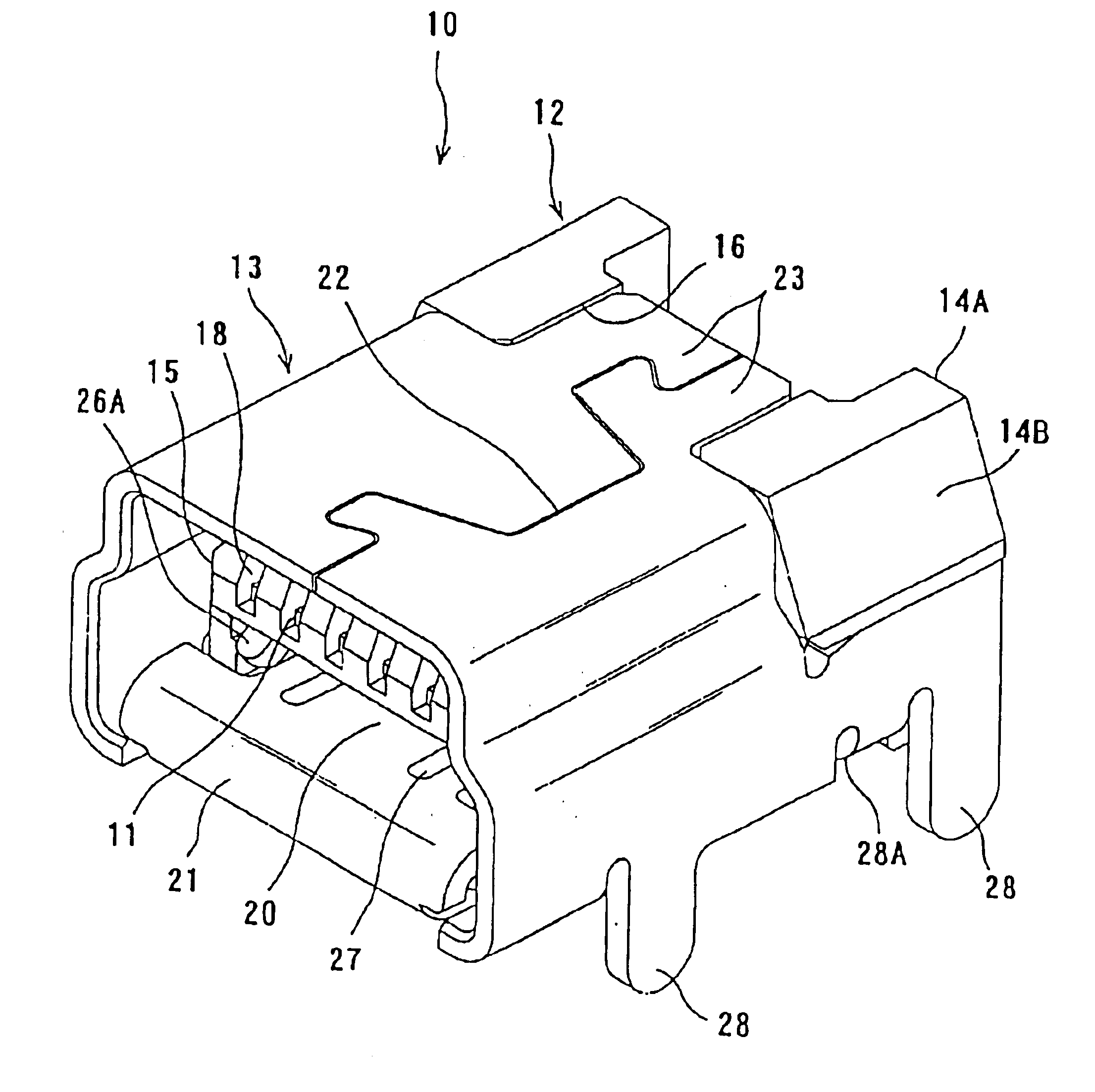
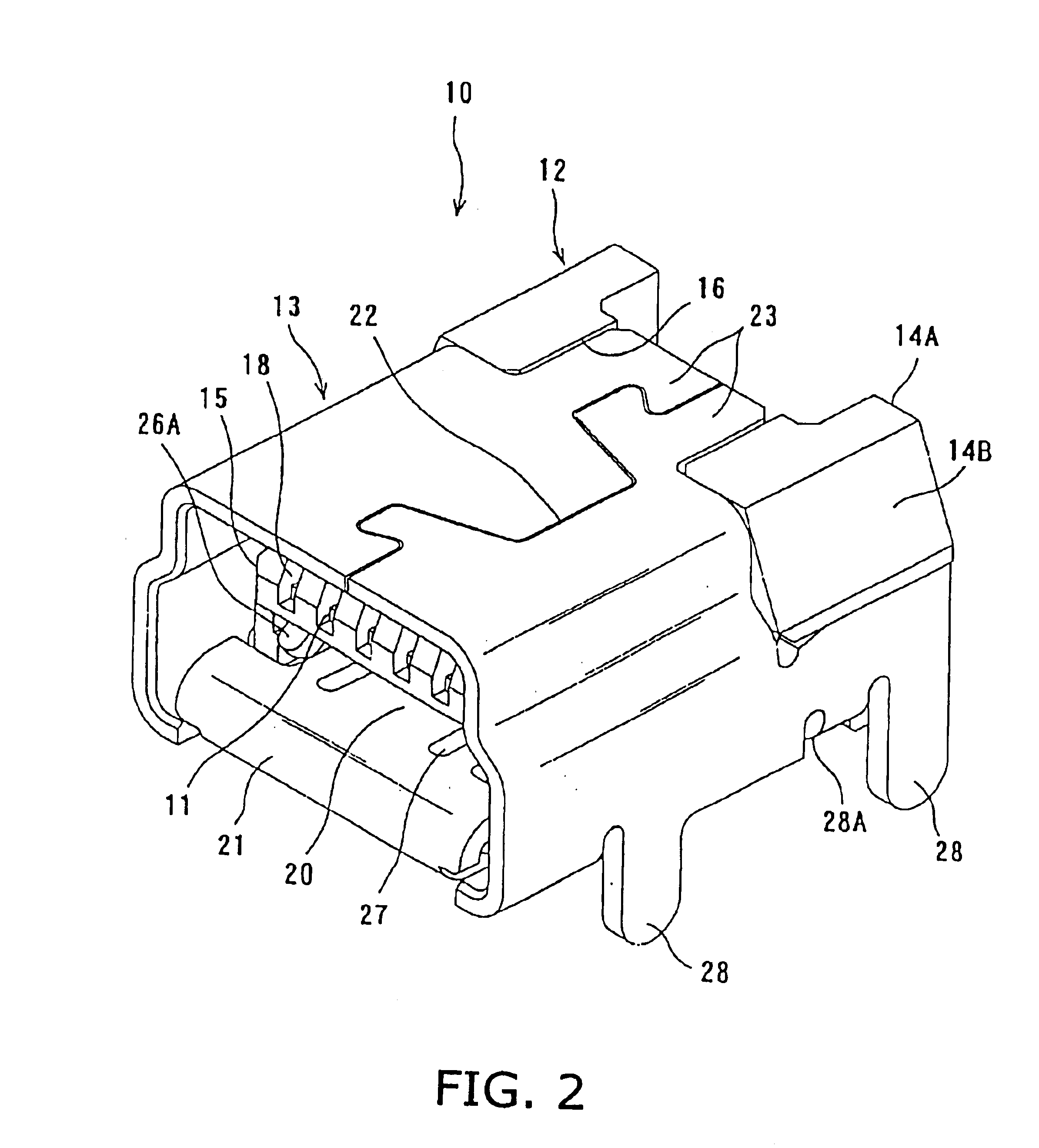
FIG. 1, reference numeral 10 denotes a receptacle connector according to an embodiment of the present invention and 30 a mating plug connector to be plugged in the receptacle connector 10.

The bottom surface of the receptacle connector 10 shown in FIG. 1 faces upwardly so that it can be fixed to the lower surface of a circuit board (not shown) of an electronic apparatus. However, the receptacle connector 10 shown in FIG. 2 and after that faces downwardly to facilitate the understanding.

As shown in FIGS. 1 and 2, the receptacle connector 10 comprises a housing 12, a plurality of terminals 11 provided in the housing 12, and a shield case 13 having a form of substantially rectangular tube (hereinafter “rectangular case”) and enclosing substantially entire part of the housing 12.

In FIGS. 2-5, the housing 12 is made of an electrically insulating material and comprises a rear section 14 h...


PUM


Abstract

An electrical connector comprises a housing (12) and a substantially rectangular case (13) made of a metal and enclosing the housing. The rectangular case includes at least one connection portion (28) on a side of a lower surface thereof for connection with a circuit board, a resilient lock piece (20) and a pair of shield pieces (26) between the upper and lower surfaces the rectangular case for engaging a mating connector. The upper surface of the case is made flat for easy assembling with the housing. The resilient lock piece has a bending portion (21), which is bent toward an inner of the rectangular case and the shield pieces are provided on sides of the resilient lock piece.

Description

BACKGROUND OF THE INVENTION1. Field of the InventionThis invention relates to an electrical connector having a housing enclosed and held by a rectangular case made of a metal, especially a USB connector.2. Description of the Related ArtAn example of the USB connector is disclosed in Japanese Patent Application Kokai Number 3076855. The UBS connector is standardized and as shown in FIG. 2 of the reference, a receptacle connector, which is fixed to a circuit board, has a metal case of which lower surface is cut downward to provided a fixing leg and part of the upper surface is cut upward to provide a locking arm. The UBS connector shown in FIG. 2 is called a “miniature-type connector”, and has a sectional shape of substantially “T” so as to have the locking arm and a shield piece in the upper side. A plug connector of the UBS connector has a display section on which information, such as the type of the connector, is indicated, and is plugged in the receptor connector with the display ...

Claims


Application Information

Patent Timeline
IPC IPC(8): H01R13/627H01R13/658H01R13/648H01R12/70H01R13/639H01R13/6582
CPCH01R13/6271H01R12/707H01R13/65802H01R13/6582H01R12/71H01R13/648
Inventor KODAMA, AKIHIRO
Owner HIROSE ELECTRIC GROUP
Why Eureka
Try Eureka