
Reactive dye printing process

a dye printing and dye technology, applied in the field of printing generally, can solve the problems of affecting the quality of dye printing, the inability to achieve high-quality images, so as to prevent premature or undetectable reaction, above the melting point of wax

Inactive Publication Date: 2005-01-11
SAWGRASS SYST INC
View PDF3 Cites 29 Cited by
  • Summary
  • Abstract
  • Description
  • Claims
  • Application Information

AI Technical Summary

Benefits of technology

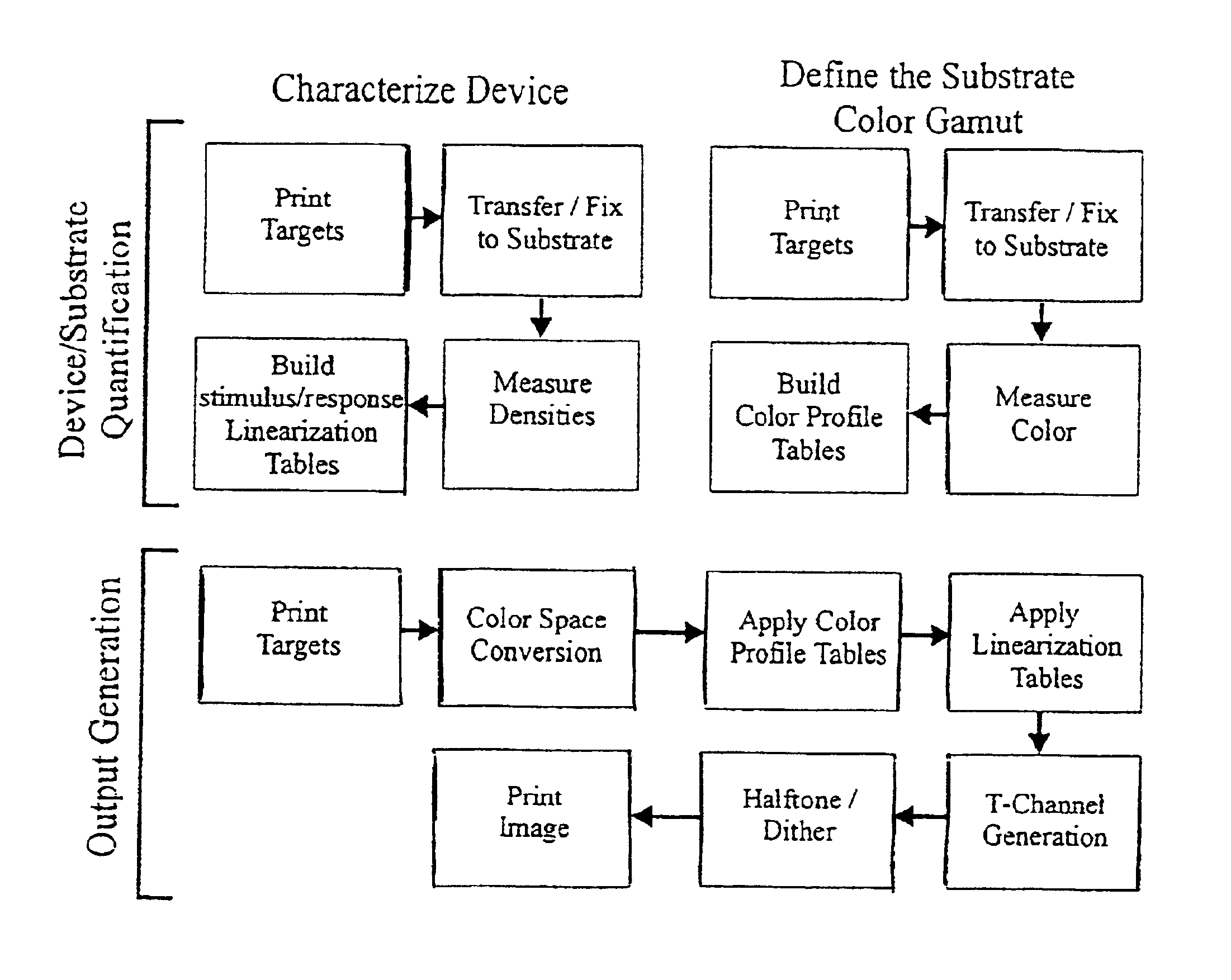
A digital printer prints an image onto an intermediate medium, which may be paper, at a relatively low temperature, so that the ink is not activated during the process of printing onto the medium. The image formed by the printed ink is transferred from the intermediate medium to a final substrate on which the image is to permanently appear, such as by the application of heat and pressure which activates the ink. The process produces an image on the final substrate which is water-fast and color-fast.

Problems solved by technology

While sublimation dyes yield excellent results when a polyester substrate is used, these dyes have a limited affinity for other materials, such as natural fabrics like cotton and wool.
Accordingly, images produced by heat activated inks comprising sublimation dyes which are transferred onto textile materials having a cotton component do not yield the high quality images experienced when images formed by such inks are printed onto a polyester substrate.
Images which are printed using sublimation dyes applied by heat and pressure onto substrates of cotton or cotton and polyester blends yield relatively poor results.
The natural tendency of the cotton fiber to absorb inks causes the image to lose its resolution and become distorted.
Liquid inks other than sublimation inks wick, or are absorbed by cotton or other absorbent substrates, resulting in printed designs of inferior visual quality, since the printed colors are not properly registered on the substrate.
The excess surface coating reduces the aesthetic quality of the printed image on the substrate.
Further, the surface coating tends to turn yellow with age, which is undesirable on white and other light colored substrates.
Thermal transfer paper can transfer an image to a final substrate such as cotton, however, this method has several limitations.
Second, such papers are heavily coated with polymeric material to bind the image onto the textile.
This material makes the transfer area very stiff and has poor dimensional stability when stretched.
Finally, the laundering durability is not improved to acceptable levels.
This bond is not durable to washing.
None of these processes are printed digitally and require pre- and after-treatments.

Method used


Image

  • Reactive dye printing process
  • Reactive dye printing process
  • Reactive dye printing process

Examples


Embodiment Construction

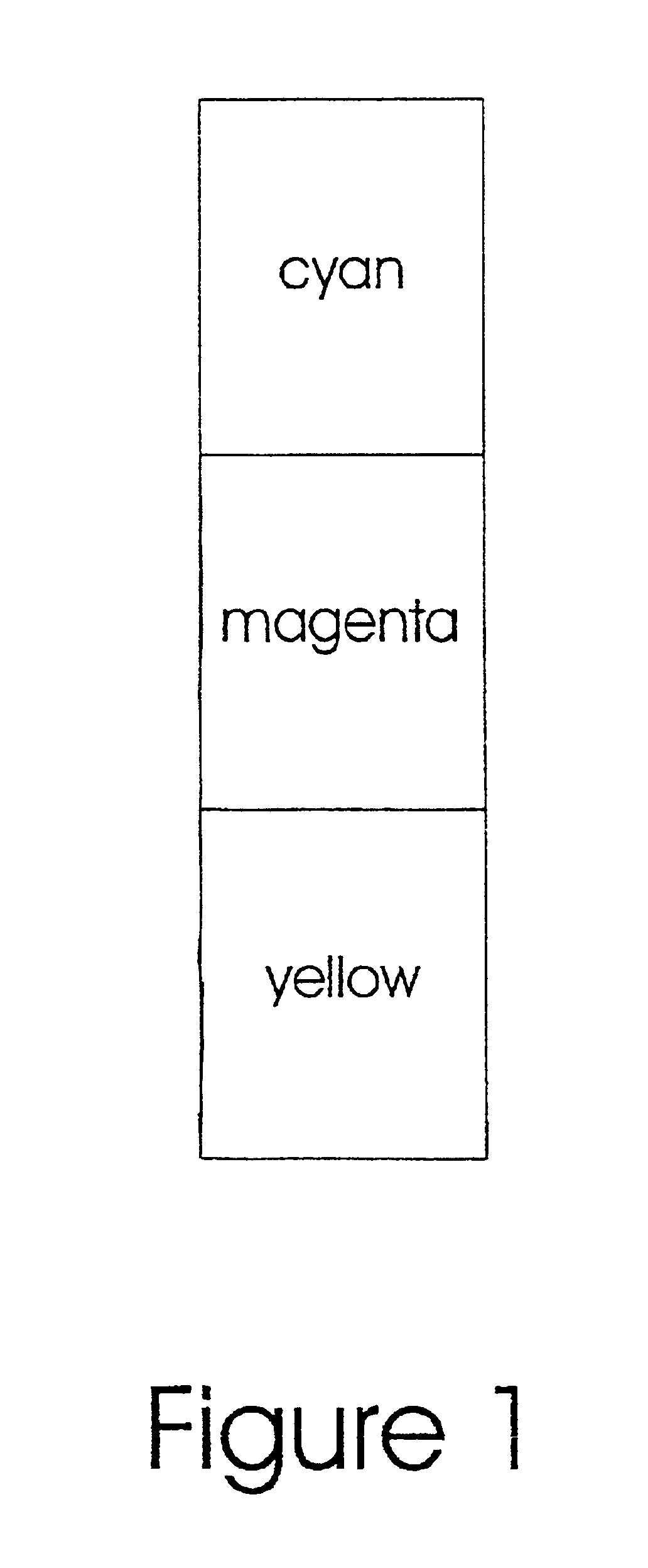
In a preferred embodiment of the present invention, a heat-melt ink ribbon is formed composed of at least one colored ink panel. A repeating sequence of colored ink panels may be used. A typical pattern of panels is yellow, magenta, and cyan (FIG. 1), although black, white, or other panels could be interposed (FIG. 2). Colorants used for such ink panels are reactive dyes, which have an affinity for the final substrate, which may be for example, cellulosic fiber, such as cotton, linen, or viscose; polyamide-fiber, such as nylon 6.6; mixtures of cellulose or polyamide with polyester; or protein fibers, such as wool and silk. The colorant(s) bonds permanently to the final substrate by forming a covalent bond between a carbon or phosphorous atom of the dye ion or molecule and an oxygen, sulfur, or nitrogen atom of a hydroxy, a mercapto, or amino group, respectively, of the final substrate.

In an additional embodiment of the invention, a combination of reactive and disperse dyes are used ...


PUM

PropertyMeasurementUnit
diameteraaaaaaaaaa
melting pointaaaaaaaaaa
temperatureaaaaaaaaaa

Abstract

A formulation and method of printing an ink or meltable ink layer having reactive dyes or mixtures of reactive dyes and disperse dyes as colorants. The ink or ink melt layer also includes an alkaline substance, a binder, and optionally, a heat-activated printing additive. Permanently bonded color images are provided by the reaction between the reactive dye and the final substrate, which may be any cellulosic, protein, or polyamide fiber material, or mixtures with polyester. Reaction occurs upon heat activation of the printed ink image.

Description

FIELD OF THE INVENTIONThis invention relates to printing generally, and more specifically, to a reactive dye which may be thermally printed from a substrate, and a method of printing the reactive dye.BACKGROUND OF THE INVENTIONWords and designs are frequently printed onto clothing and other textile materials, as well as other objects. Common means of applying such designs, to objects include the use of silk screens, and mechanically bonded thermal transfers. The silk screen process is well known in the art, and an example of a mechanical thermal bonding process to textile materials is described in Hare, U.S. Pat. No. 4,224,358.The use of digital computer technology allows a virtually instantaneous printing of images. For example, video cameras or scanning may be used to capture an image to a computer. The image may then be printed by a computer driven printer, including thermal, ink jet, and laser printers. Computer driven printers are readily available which will print in multiple ...

Claims


Application Information

Patent Timeline
Patent Type & Authority Patents(United States)
IPC IPC(8): B41M5/025B41M5/50B41M7/00B41M5/52D06P5/24D06P5/20D06P3/10D06P3/58D06P3/82D06P3/24D06P3/66D06P3/54D06P3/34D06P3/14D06P3/04B41J31/00B41J2/325B41M5/382B41M5/385B41M5/39B41M5/392B41M5/395D06P1/382D06P5/00D06P5/26G01D15/16
CPCB41M5/0256D06P5/2077B41M5/38257B41M5/385B41M5/392B41M5/395B41M5/52B41M7/00D06P5/003D06P5/007B41M5/345D06P3/10D06P3/148D06P3/248D06P3/54D06P3/66D06P3/8214D06P3/8252
Inventor WAGNER, BARBARA J.XU, MING
Owner SAWGRASS SYST INC
Learn More