
Brake actuator

a technology of brake actuator and actuator, which is applied in the direction of brake system, braking system, railway braking system, etc., can solve the problems of high cost, and large braking force generator, and achieve the effect of increasing safety

Inactive Publication Date: 2005-01-11
KNORR BREMSE SYST FUR SCHIENENFAHRZEUGE GMBH
View PDF9 Cites 15 Cited by
  • Summary
  • Abstract
  • Description
  • Claims
  • Application Information

AI Technical Summary

Benefits of technology

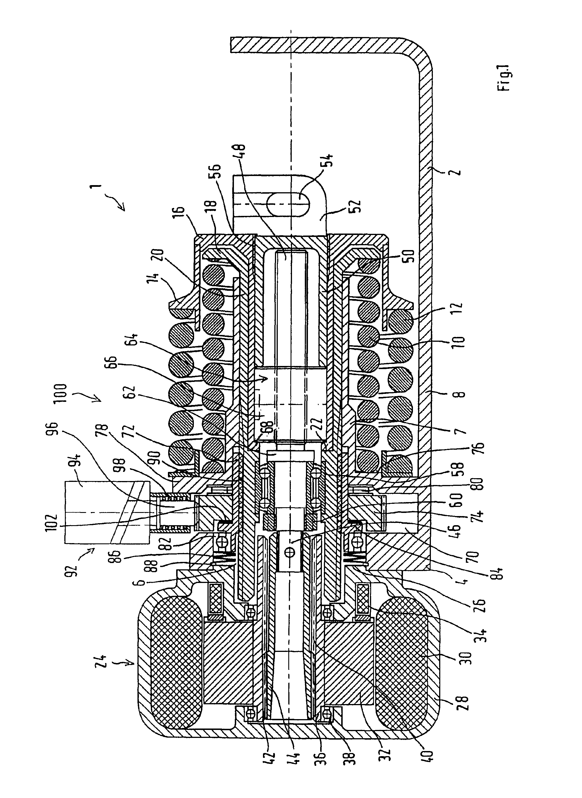
An additional energy accumulator in the form of the accumulator-type spring and the braking force generator are designed such that the force to be applied by the braking force generator during a braking for generating a defined braking pressure in a defined operating point, which is greater than zero and smaller than the maximal braking force, amounts to zero. Thus the braking force generator does not have to generate an additional braking force in the defined operating point. Rather, the braking force is then generated by the accumulator-type spring alone. For reaching a maximal braking force, the braking force generator assists the accumulator-type spring. For generating lower braking forces, the braking force generator counteracts the force of the accumulator-type spring. The braking force generator therefore acts as only an assisting drive in both load directions for applying the maximal braking force as well as for releasing the brake. The system thereby combines important advantages of a passive braking system with those of an active braking system. However, an accumulator-type spring for the brake application can be smaller than in a purely passive braking system because it does not have to apply the maximal braking force alone but together with the braking force generator. On the other hand, the braking force generator, for example, an electric motor, may also have smaller dimensions than in the case of purely active brake systems because also the braking force generator generates the braking force not alone but together with the accumulator-type spring.
The accumulator-type spring can be activated jointly with the one energy accumulator in the event of an emergency and / or parking braking in the brake application direction. Thus, it contributes, not only during service brakings but also during parking and / or emergency brakings, to the generating of braking force. For this reason, not only the braking force generator but also the one energy accumulator may have smaller dimensions. Furthermore, safety is increased because, as a result of the accumulator-type spring as an additional energy accumulator, a redundancy exists in the case of parking and / or emergency brakings.

Problems solved by technology

The braking force generator is therefore relatively large and consequently also relatively heavy and expensive.

Method used


Image

  • Brake actuator
  • Brake actuator
  • Brake actuator

Examples


Embodiment Construction

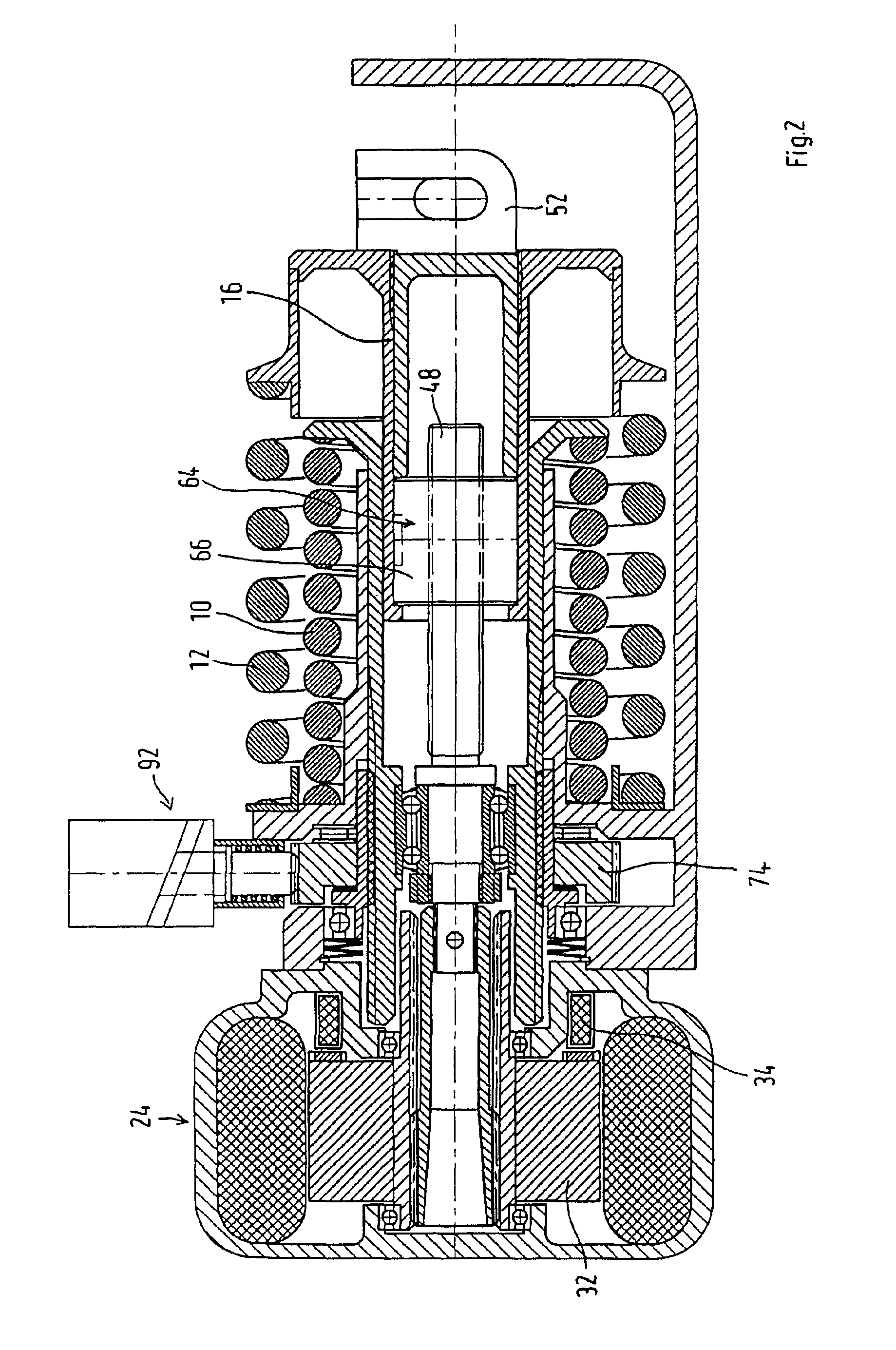
The preferred embodiment of a brake actuator which, as a whole, is marked by reference number 1 in FIG. 1 and is illustrated in a release position, is used as a driving unit of an electro-mechanical brake application device of a rail vehicle. The brake actuator 1 has an essentially hollow-cylindrical actuator housing 2 which in FIG. 1 is illustrated in a broken-off fashion and which is closed off by a lid section 4 toward an axial end. The lid section 4 has a centered bore 6. Starting from the lid section 4, the actuator housing 2 has an essentially double-walled construction. An internal accumulator-type spring 10 and an external accumulator-type spring 12 coaxial thereto are arranged in the space between an interior wall 7 and an exterior wall 8. The external accumulator-type spring 12 encloses the internal accumulator-type spring 10.

The accumulator-type springs 10, 12 are shown as coil springs and are in each case supported by one of their ends at the lid section 4. The external ...


PUM


Abstract

The invention relates to a brake actuator, especially for a rail vehicle brake, comprising a service brake unit with a brake force generator for applying and / or releasing the brake, an accumulator brake unit with an energy accumulator device for accumulating and delivering energy for applying the brake as an operative emergency brake and / or as a parking brake, and a force conversion device for converting the energy that is provided by the brake force generator and / or the energy accumulator device into a brake application movement. The invention provides that the brake actuator has an additional energy accumulator device for accumulating and delivering energy for applying and / or releasing the brake. The additional energy accumulator device and the brake force generator can be designed in such a way that the force required of the brake force generator during a braking operation in order to generate a defined brake application force level that is greater than zero but less than the maximum brake force is zero.

Description

BACKGROUND AND SUMMARY OF THE INVENTIONState of the ArtThe invention is based on a brake actuator, particularly for a rail vehicle brake.Essentially, three braking systems are currently used in the rail vehicle field: pneumatic or electro-pneumatic braking systems, hydraulic or electro-hydraulic braking systems as well as mechanical or electro-mechanical braking systems. The braking system may be constructed as an active or passive braking system, depending on whether the force of the brake actuator is to be applied for an engaging (active braking system) or a releasing of the brake (passive braking system). In the event of operating disturbances, in the case of pneumatic systems, an energy accumulation takes place in compressed-air reservoirs; in the case of hydraulic systems, an energy accumulation takes place in hydraulic reservoirs; and in the case of mechanical systems, an energy accumulation takes place in the form of accumulator-type springs.From US Patent Document U.S. Pat. ...

Claims


Application Information

Patent Timeline
Patent Type & Authority Patents(United States)
IPC IPC(8): B61H13/00F16D65/36F16D65/14B60T13/74F16D65/28
CPCB61H13/005F16D65/28F16D2121/24F16D2127/06F16D2125/585F16D2127/008F16D2125/40
Inventor GRUNDWURMER, RICHARDSTALTMEIR, JOSEFVOHLA, MANFRED
Owner KNORR BREMSE SYST FUR SCHIENENFAHRZEUGE GMBH
Learn More