
Method of compressing digital images

a digital image and compression factor technology, applied in the field of compressing digital images, can solve the problems of high computation time, large power consumption of known methods, and difficult algorithmic compression factor control, and achieve the effect of reducing the number of known methods

Inactive Publication Date: 2005-01-04
STMICROELECTRONICS SRL
View PDF12 Cites 13 Cited by
  • Summary
  • Abstract
  • Description
  • Claims
  • Application Information

AI Technical Summary

Benefits of technology

The present invention provides a method for compressing a digital image by using a matrix of elements, each containing multiple digital components of different types. The method involves obtaining an incomplete image, splitting the image into blocks, and calculating a group of DCT coefficients for each block. These coefficients are then quantized using a gain factor to achieve a target compression factor. The method also includes determining an energy measure of the incomplete image and estimating the gain factor as a function of this energy measure. The invention also provides a device for compressing a digital image and a digital still camera comprising this device. The technical effects of the invention include improved image quality and reduced file size.

Problems solved by technology

This problem is particularly perceived in digital still cameras; in fact, in this case it must be ensured that a minimum number of compressed digital images can be stored onto the memory of the camera, in order to guarantee that a minimum number of photos can be taken by the camera.
The compression factor control is quite difficult in algorithms, such as the JPEG, wherein the size of the compressed digital image depends on the content of the corresponding original digital image.
The methods known in the art require a high computation time, so that they are quite slow.
Moreover, the known methods involve a considerable power consumption; this drawback is particular acute when the compression method is implemented in a digital still camera, or other portable devices which are supplied by batteries.

Method used


Image

  • Method of compressing digital images
  • Method of compressing digital images
  • Method of compressing digital images

Examples


Embodiment Construction

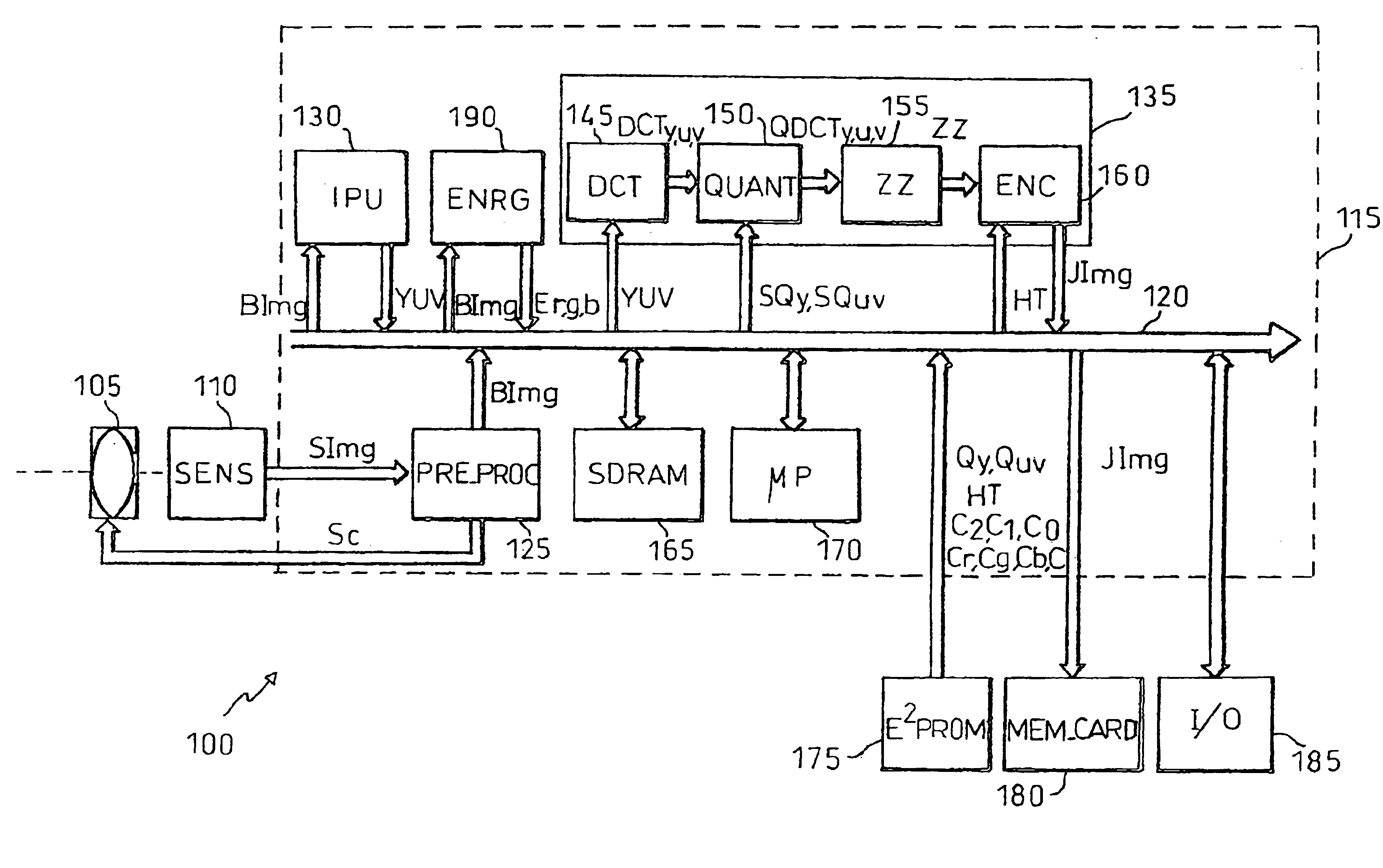
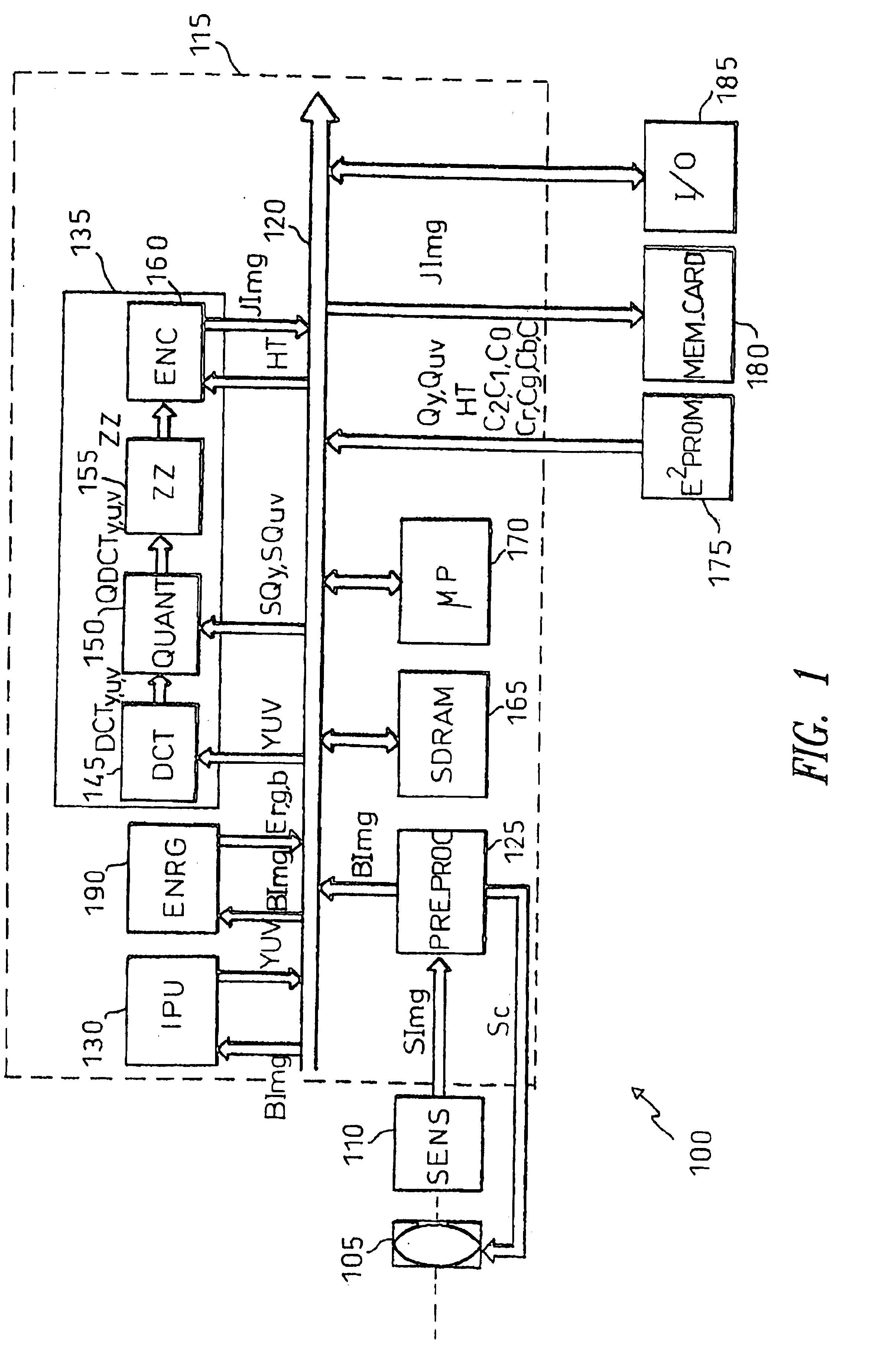
With reference in particular to FIG. 1, this shows a digital still camera 100 for taking digital images representative of real scenes. A digital image is constituted by a matrix with N rows and M columns (for example, 640 rows by 480 columns); each element of the matrix consists of several digital values (for example three values each one of 8 bits, ranging from 0 to 255) representative of respective optical components of a pixel.

The camera 100 includes an image-acquisition unit 105 formed by a diaphragm and a set of lenses for transmitting the light corresponding to the image of the real scene onto a sensor unit (SENS) 110. The sensor unit 110 is typically constituted by a Charge-Coupled Device (CCD); a CCD is an integrated circuit which contains a matrix of light-sensitive cells, each one generating a voltage the intensity of which is proportional to the exposure of the light-sensitive cell. The voltage generated by each light-sensitive cell is supplied to an analog / digital conver...


PUM


Abstract

A method compresses a digital image including a matrix of elements each one including a plurality of digital components of different type representing a pixel. The method includes the steps of providing an incomplete digital image wherein at least one component is missing in each element, obtaining the digital image from the incomplete digital image, splitting the digital image into a plurality of blocks and calculating, for each block, a group of DCT coefficients for the components of each type, and quantizing the DCT coefficients of each group using a corresponding quantization table scaled by a gain factor for achieving a target compression factor. The method further comprises the steps of determining an energy measure of the incomplete digital image and estimating the gain factor as a function of the energy measure, the function being determined experimentally according to the target compression factor.

Description

BACKGROUND OF THE INVENTION1. Field of the InventionThe present invention relates to a method of compressing digital images.2. Description of the Related ArtDigital images are commonly used in several applications such as, for example, in digital still cameras (DSC). A digital image consists of a matrix of elements, commonly referred to as a bit map; each element of the matrix, which represents an elemental area of the image (a pixel or pel), is formed by several digital values indicating corresponding components of the pixel.Digital images are typically subjected to a compression process in order to increase the number of digital images which can be stored simultaneously, such as onto a memory of the camera; moreover, this allows transmission of digital images (for example in the INTERNET) to be easier and less time consuming. A compression method commonly used in standard applications is the JPEG (Joint Photographic Experts Group) algorithm, described in CCITT T.81, 1992.In the JP...

Claims


Application Information

Patent Timeline
Patent Type & Authority Patents(United States)
IPC IPC(8): H04N7/30H04N5/235H04N5/232H04N19/122H04N19/126H04N19/14H04N19/149H04N19/18H04N19/186H04N19/42H04N19/60
CPCH04N5/23212H04N5/2351H04N19/149H04N19/122H04N19/42H04N19/126H04N19/14H04N19/186H04N19/18H04N19/60H04N23/673H04N23/71H04N25/134
Inventor BRUNA, ARCANGELOMANCUSO, MASSIMOGALLUZZO, AGOSTINO
Owner STMICROELECTRONICS SRL
Learn More