Automated disk-ejection apparatus and disk array having the same
a disk array and automatic technology, applied in the direction of casings/cabinets/drawers, casings/cabinets/drawers, electric devices, etc., can solve the problems of over-design using locks, affecting the service life of the company, and affecting the design. , to achieve the effect of convenient loading or unloading
- Summary
- Abstract
- Description
- Claims
- Application Information
AI Technical Summary
Benefits of technology
Problems solved by technology
Method used
Image
Examples
first embodiment
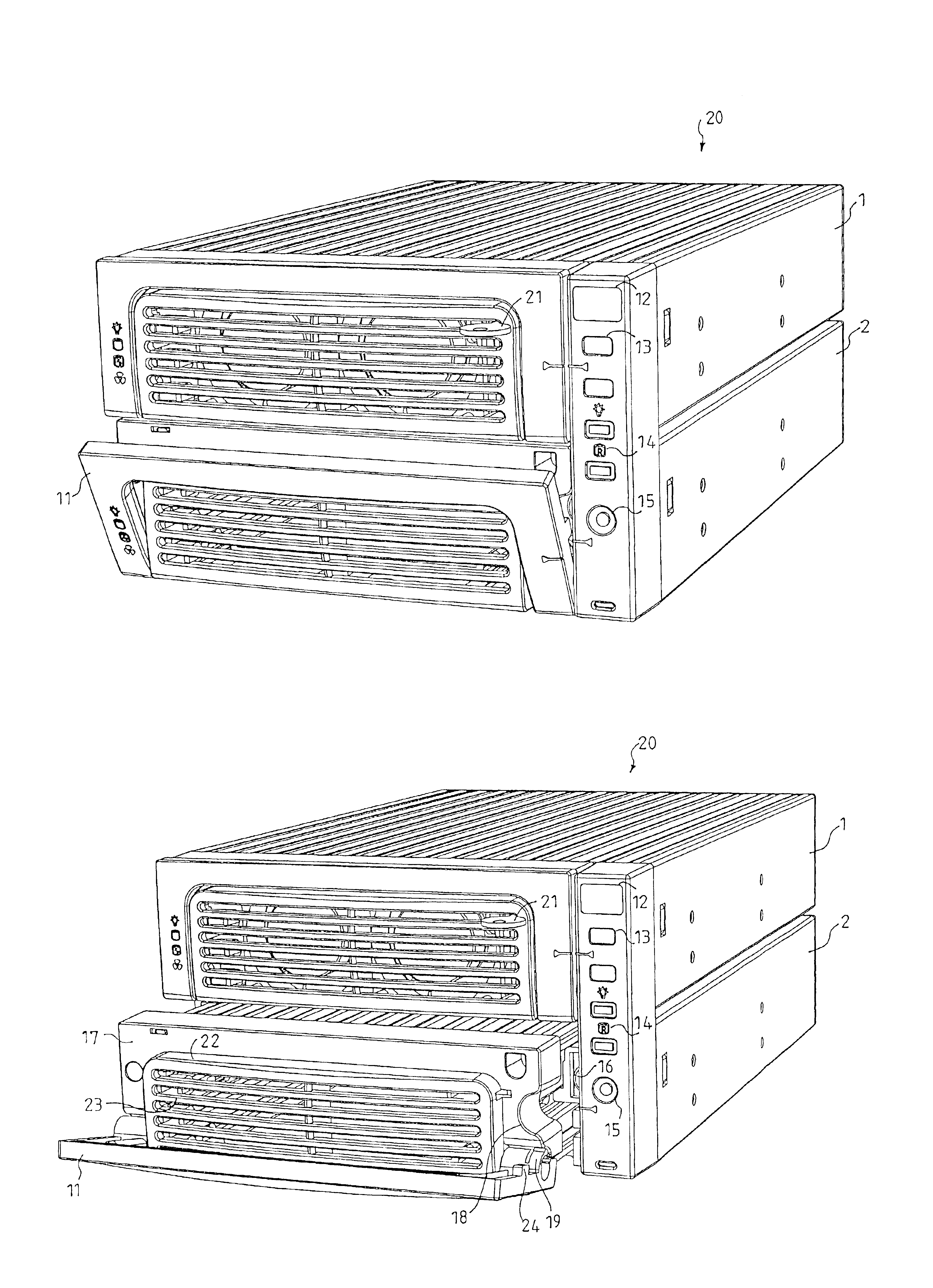
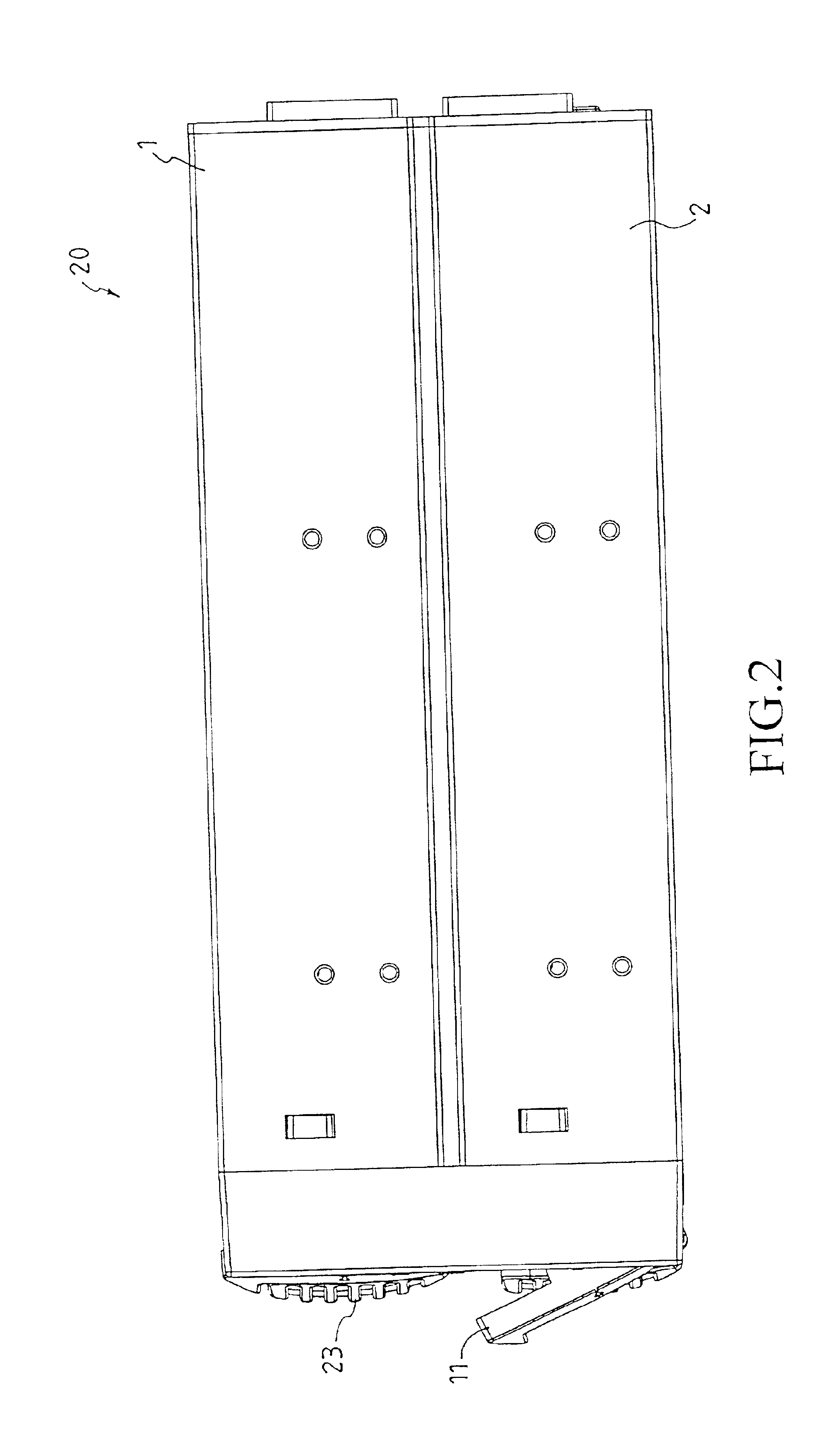
FIG. 4 shows the system according to the present invention. The disk box 2 comprises a panel 17. The handle 11 for pulling out the disk box 2 is connected to the disk box panel via a pivot 19. At one vertical side edge (right side in FIG. 4) of the panel 17, there is a groove 18 for accommodating a protrusion 24 of the handle 11, as well as for being the passage of the pushing mechanism (described later). The pushing mechanism 16 is controlled by a control circuit. The control circuit can be designed such that while a failure of a disk drive in the disk box 2 is detected, or the disk drive needs to be replaced, the control circuit controls and drives the pushing mechanism 16 by using a solenoid valve or an electric motor. The pushing mechanism 16 thus passes through the side groove 18 of the panel 17 to push the handle 11. The handle 11 can rotate to an eject state for a user to pull out the disk box 2.
In the system shown in FIG. 4, the handle 11 is connected to the disk box 2 via a...
second embodiment
FIG. 5 illustrates a disk array system in accordance with the present invention. The disk array system 30 comprises disk boxes 31 and 32. Each of the disk boxes 31 and 32 comprises a rotatable panel 34. The panel 34 is connected to the disk box via a side pivot 35. It is clearly shown in FIG. 5 that the pushing mechanism 33 is used to push the rotatable panel 34 of the disk box. In a preferred embodiment, a solenoid valve or an electric motor can be used to release a latch of the panel 34 and push the panel 34 to rotate along the pivot 35, for a user to pull (or push) the panel 34 to withdraw (or restore) the disk box 31.
third embodiment
FIG. 6 illustrates a disk array system in accordance with the present invention, in which the disk array system 40 includes disk boxes 41 and 42. Each disk box 41 or 42 has a rotatable panel 44, and the panel 44 is connected to the disk box via a pivot 45 located at the lower part of the front surface of the disk box. In the embodiment disclosed in FIG. 6, a pushing mechanism is used to push the rotatable panel 44. After the panel 44 rotates along the pivot 45 to an inoperative state, a user can pull (or push) a handle 46 on the disk box 42 to withdraw (or inserst) the disk box 41.
Furthermore, because the pushing mechanisms 33 and 43 shown in FIGS. 5 and 6 are located at the front surfaces of housings of the disk array systems 30 and 40, the pushing mechanisms will not move along with the movement of each disk box 31, 32, 41 or 42. However, it should be noted that pushing mechanisms 33 or 43 can be located at the front surfaces of the disk boxes 31, 32, 41 and 42. Under this circums...
PUM
| Property | Measurement | Unit |
|---|---|---|
| processing speed | aaaaa | aaaaa |
| stability | aaaaa | aaaaa |
| shape | aaaaa | aaaaa |
Abstract
Description
Claims
Application Information
 - R&D
- Intellectual Property
- Life Sciences
- Materials
- Tech Scout
- Unparalleled Data Quality
- Higher Quality Content
- 60% Fewer Hallucinations
Browse by: Latest US Patents, China's latest patents, Technical Efficacy Thesaurus, Application Domain, Technology Topic, Popular Technical Reports.
© 2025 PatSnap. All rights reserved.Legal|Privacy policy|Modern Slavery Act Transparency Statement|Sitemap|About US| Contact US: help@patsnap.com


