
Mobile station equipment, base station equipment, exchange, and mobile communication system

a mobile station and equipment technology, applied in the field base station equipment, exchange, and mobile communication system, can solve the problems of increasing the cost, reducing the cost effectiveness of mobile station equipment, and unable to prevent the aforementioned accidents reliably, so as to achieve efficient and reliable prevention of accidents

Inactive Publication Date: 2004-11-09
FUJITSU LTD
View PDF12 Cites 78 Cited by
  • Summary
  • Abstract
  • Description
  • Claims
  • Application Information

AI Technical Summary

Benefits of technology

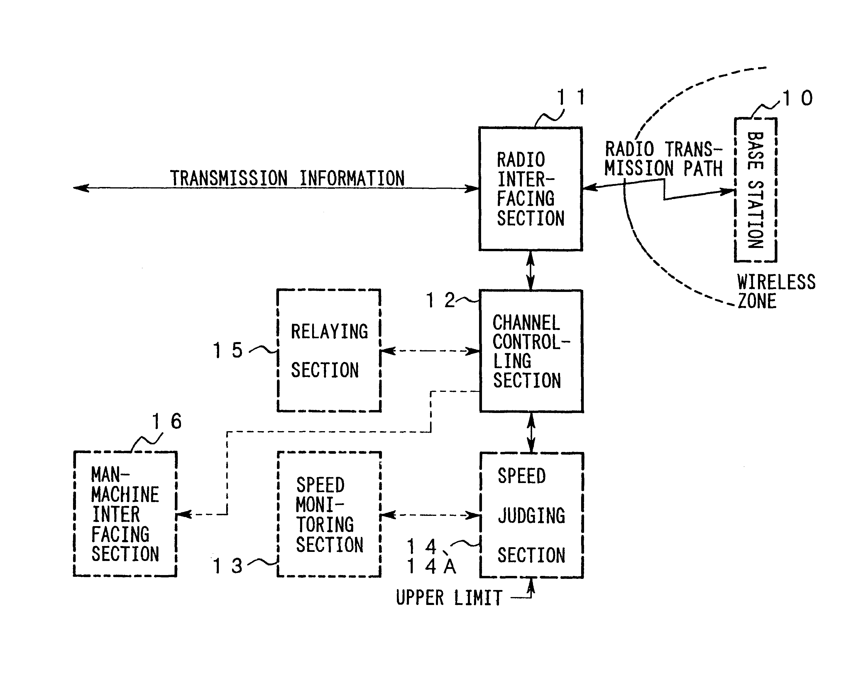
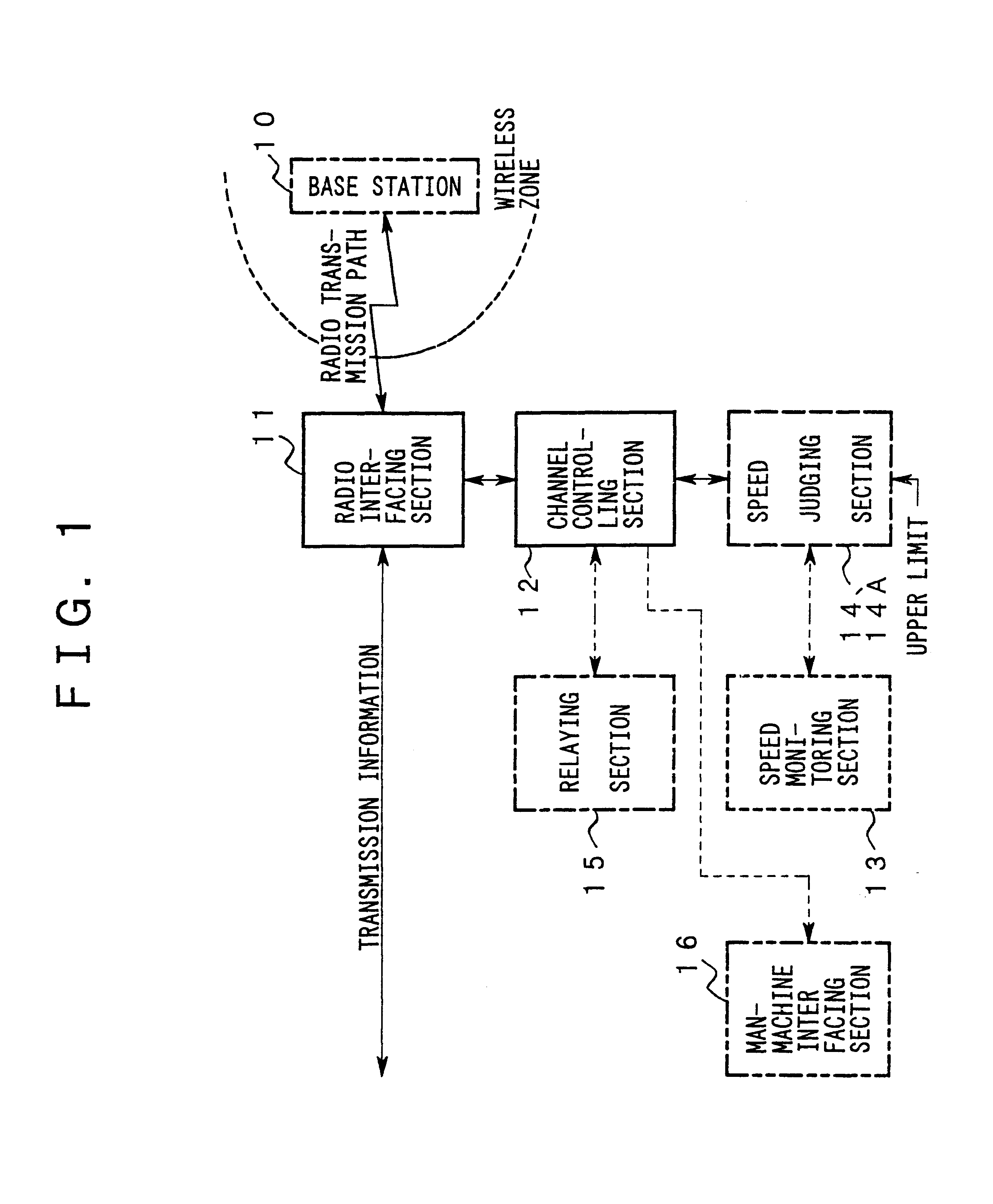
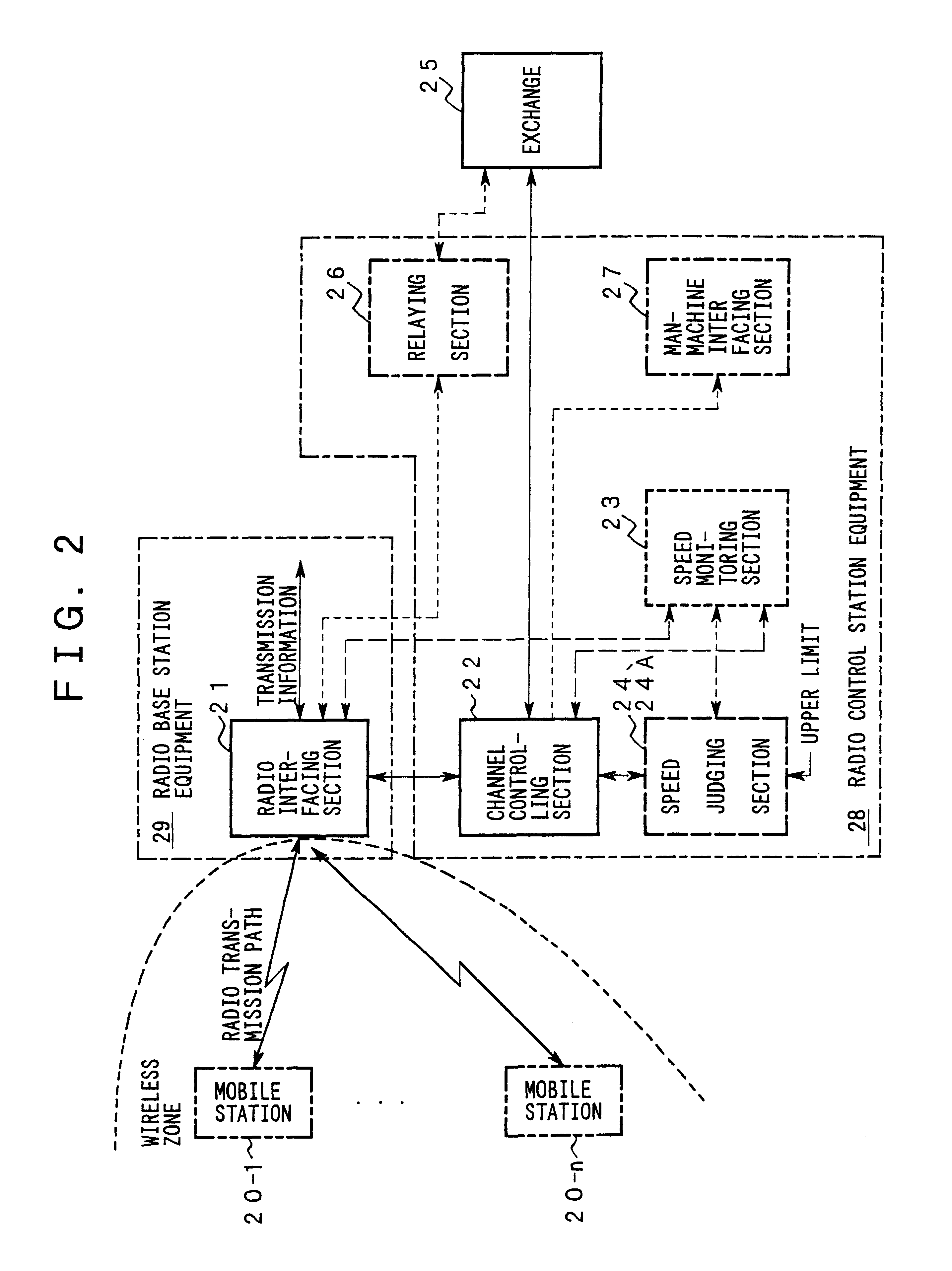
to provide technologies for efficiently and reliably preventing accidents which would normally be caused by some operation by a human operator in response to a call occurring while the unit or vehicle is moving at a high speed.
In this base station equipment, it is possible to flexibly adapt itself to a zone configuration or channel allocation, as well as to an area in which mobile stations can be located and to the distribution of these mobile stations in this area. Consequently, the service quality is improved and maintained high.

Problems solved by technology

In particular, the mobile unit or vehicle carrying the mobile station equipment 80 is able to run at a high speed without attaching the connector and, therefore, prevention of the aforementioned accidents cannot be accomplished reliably due to lack of driver's safety mind or human errors.
However, this configuration lowers of the cost effectiveness of the mobile station equipment and increases the cost.
Although this configuration may be applied to newly manufactured mobile station equipment, it is impossible to apply it to already operating mobile station equipment or to those kinds of mobile station equipment which are not operated but appear on the market.
Consequently, it has not been assured that the aforementioned accidents are prevented.

Method used


Image

  • Mobile station equipment, base station equipment, exchange, and mobile communication system
  • Mobile station equipment, base station equipment, exchange, and mobile communication system
  • Mobile station equipment, base station equipment, exchange, and mobile communication system

Examples


first embodiment

FIG. 6 is a flow chart illustrating the operation of the present invention.

The operation of the present embodiment is described below by referring to FIGS. 5 and 6.

The TX / RX part 71 measures the frequency at which a receiving wave, of receiving waves arrive at antennas 85M-1 and 85M-2 from radio base station equipment 81, that is selected according to the switching diversity described above is switched. The TX / RX part 71 notifies the processor 72 of the frequency and whether the frequency is greater or smaller than a given upper limit. The processing performed by the TX / RX part 71 will be hereinafter referred to as "speed measuring processing M".

The processor 72 recognizes the period for which the frequency exceeds the upper limit, according to the notice (FIG. 6(1)). The processing for recognizing the period will hereinafter be referred to as "high-speed recognition processing M".

The processor 72 outputs a message to the operation / indication part 90 to display the message (FIG. 6(2...

second embodiment

the present invention is described now.

The difference in structure between the present embodiment and the prior art example shown in FIG. 14 is that radio base station equipment 73 and radio control station equipment 74 are mounted instead of the radio base station equipment 81 and the radio control station equipment 83, respectively.

The difference in structure between the radio base station equipment 73 and the radio base station equipment 81 is that a TX / RX part 75 and a transmission path interfacing part 76 are mounted instead of the TX / RX parts 86B and the transmission path interfacing part 91B, respectively.

The difference between the radio control station equipment 74 and the radio control station equipment 83 is that a processor 77 is mounted instead of the processor 87C.

FIG. 7 is a flow chart illustrating the operation of the second embodiment of the present invention.

The operation of the present embodiment is hereinafter described by referring to FIGS. 5 and 7.

In the radio b...

third embodiment

the present invention is hereinafter described.

The difference in structure between the present embodiment and the second embodiment is that radio control station equipment 74A and an exchange 78 are mounted instead of the radio control station equipment 74 and the exchange 84, respectively.

The difference in structure between radio control station equipment 74A and radio control station equipment 74 is that a processor 87C is mounted instead of the processor 77.

The difference in structure between the exchanges 78 and 84 is that the processor 79 is mounted instead of the processor 87E shown in FIG. 14.

FIG. 8 is a flow chart illustrating the operation of the third embodiment of the present invention.

The operation of the present embodiment is hereinafter described with reference to FIGS. 5 and 8.

In the radio base station equipment 73, the TX / RX part 75 demodulates the receiving waves that reached to an antenna 85B from the mobile station equipment 80 to create a baseband signal, measure...


PUM


Abstract

Mobile station equipment, base station equipment, and an exchange equipped with all or some units for monitoring the speed of a mobile station, making a judgment whether or not the speed exceeds a given threshold value, and restricting both or at least one of channel control and call processing regarding a call occurring at the corresponding mobile station. These mobile station equipment, base station equipment, and exchange operate alone or associate with each other through radio transmission paths or other links. Further a mobile communication system may include these mobile station equipment, base station equipment, and exchange. In the above equipment exchange, accidents normally caused by some operation of an operator on the mobile station equipment in response to a call occurring in the mobile station equipment moving at a high speed are prevented efficiently and reliably.

Description

1. Field of the InventionThe present invention relates to mobile station equipment that is carried on a mobile unit or in a mobile vehicle or carried by a subscriber to offer communications services to the subscriber. The invention also relates to base station equipment for forming a wireless zone in a region where a mobile station can be positioned and providing channel control in the wireless zone. Furthermore, the invention relates to an exchange that associates with this base station equipment and performs call processing. In addition, the invention relates to a mobile communication system composed of such mobile station equipment, base station equipment, and exchange.2. Description of the Related ArtIn recent years, mobile communication systems have become rapidly widespread because of competition among communication service providers and liberalization of the market. Therefore, subscribers receive various kinds of communication services through in-vehicle terminals, as well as...

Claims


Application Information

Patent Timeline
Patent Type & Authority Patents(United States)
IPC IPC(8): H04Q7/30H04Q7/38H04W88/08
CPCH04W88/08
Inventor MARUYAMA, JYOJI
Owner FUJITSU LTD
Learn More