
Method and apparatus for preventing underflow and overflow across an asynchronous channel

a technology of asynchronous communication and asynchronous channels, applied in the direction of synchronisation signal speed/phase control, data switching networks, instruments, etc., can solve the problems of packet overflow or underflow packet overflow problem, etc., to reduce the complexity of the solution and eliminate the control split

Inactive Publication Date: 2004-11-02
VALTRUS INNOVATIONS LTD +1
View PDF13 Cites 26 Cited by
  • Summary
  • Abstract
  • Description
  • Claims
  • Application Information

AI Technical Summary

Benefits of technology

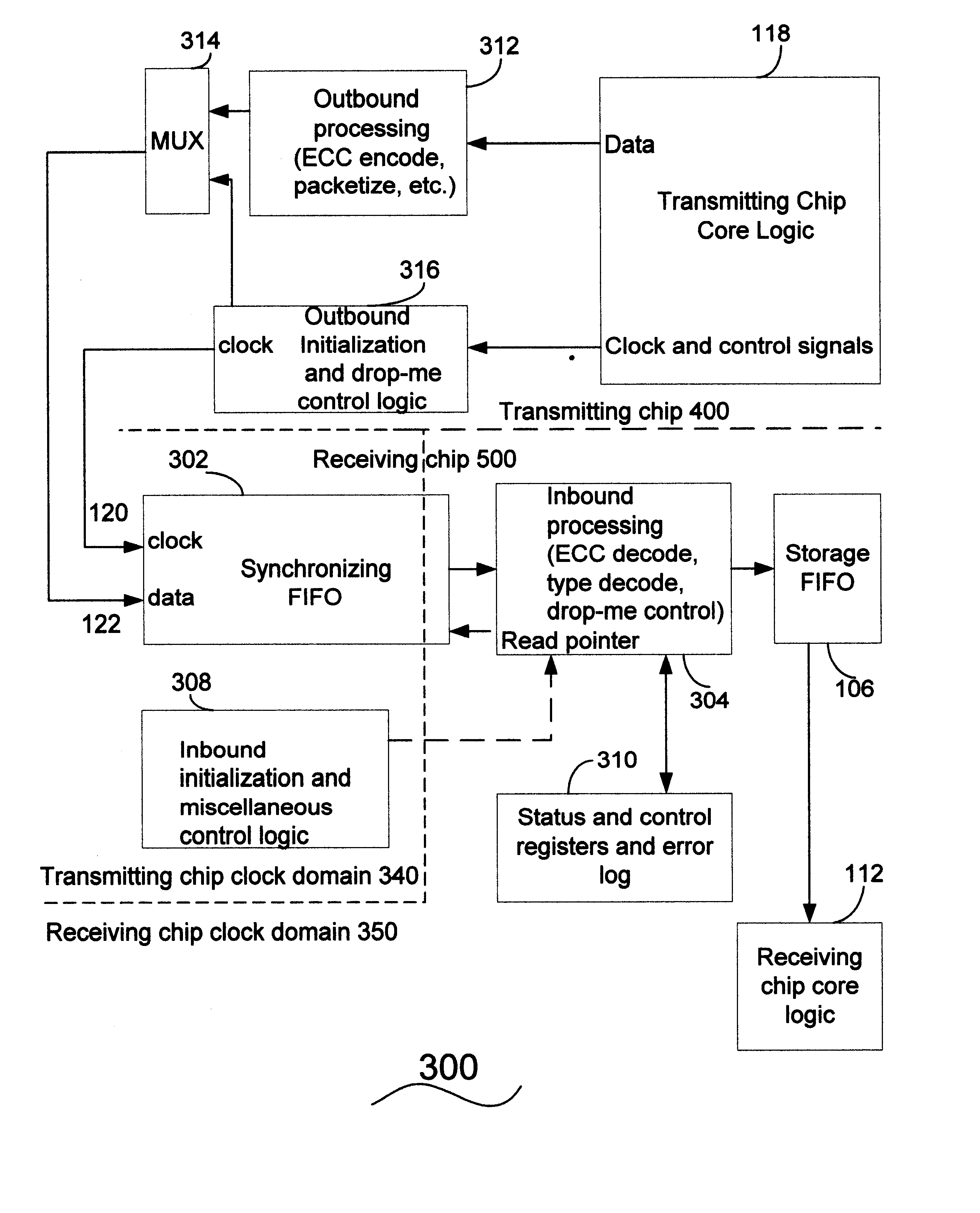
is to provide a simple implementation that solves both the overflow problem and the underflow problem using the same mechanism, and which reduces the solution complexity by elimination of the control split between the receiving chip and transmitting chip clock domains.
A first aspect of the invention is directed to a method for preventing packet underflow and packet overflow for packets sent across an asynchronous link between a transmitter and a receiver, wherein the receiver includes a buffer that can store a number of packets greater than an ideal number of packets. The method includes sending a predetermined number of drop-me warning packets from the transmitter to the receiver across the asynchronous link, sending one or more drop-me packets from the transmitter to the receiver across the asynchronous link, receiving the predetermined number of drop-me warning packets and the one or more drop-me packets in the buffer, compensating for packet overflow when the number of packets in the buffer is greater than the ideal number of packets by skipping at least one drop-me packet in the buffer, so that the ideal number of packets is substantially maintained in the buffer, and compensating for packet underflow when the number of packets is less than the ideal number of packets by stalling access to the buffer for one or more clock cycles, so that the ideal number of packets is substantially maintained in the buffer.

Problems solved by technology

In a system with multiple integrated circuit (IC) chips operating at different core frequencies, if the transmitting chip clock frequency is different from the receiving chip clock frequency, there may be packet overflow or underflow problems.
A packet overflow problem occurs when the transmitting chip clock frequency is higher than the receiving chip clock frequency, and some packets are dropped at the receiving chip.
A packet underflow problem occurs when the transmitting chip clock frequency is lower than the receiving chip clock frequency, and the receiving chip has some clock cycles when there are no valid data packets from the transmitting chip.
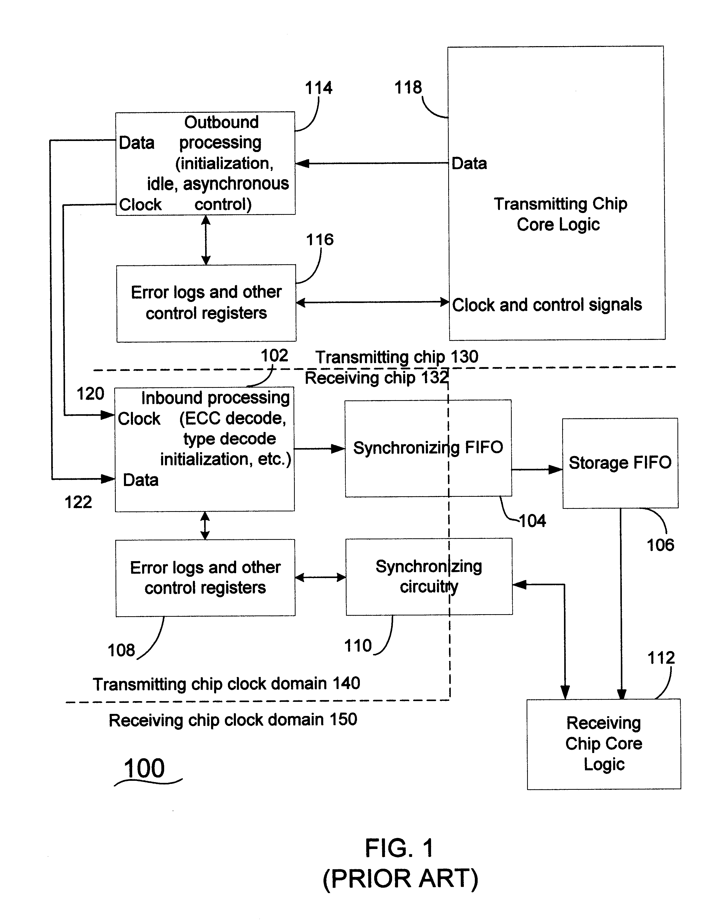
This requires a significant amount of circuitry in the receiving chip that is controlled by the transmitting chip's clock.
One drawback of this prior art approach is that the control circuitry gets split between the two clock domains, making the design complex, since the two clock domains have to work together in tandem.
Therefore, prior art solutions for overflow and underflow packet problems require separate hardware and software for overflow and underflow, with hardware in the packet path both before and after the synchronizing FIFO buffer, and require substantially continuous processing of the packets with this hardware and software, even in the middle of transactions.
There are several drawbacks to this prior art approach.
This extra circuitry introduces greater complexity into the design.
The system software has to operate successfully despite these possibilities; this can require very complex software that is difficult to write and difficult to debug.
This is also not a good solution from a high reliability / availability perspective, since the transmitting chip 130 not only affects the link to which the receiving chip 132 is connected, it also affects parts of the receiving chip 132, rendering these parts inaccessible.
However, this will significantly complicate the design.
In addition, increasing design complexity of a system (and the number of components that can fail) generally reduces the overall reliability of the system.

Method used


Image

  • Method and apparatus for preventing underflow and overflow across an asynchronous channel
  • Method and apparatus for preventing underflow and overflow across an asynchronous channel
  • Method and apparatus for preventing underflow and overflow across an asynchronous channel

Examples


Embodiment Construction

This invention provides an improved method and apparatus for asynchronous communication between a transmitting chip and a receiving chip with different core clock frequencies.

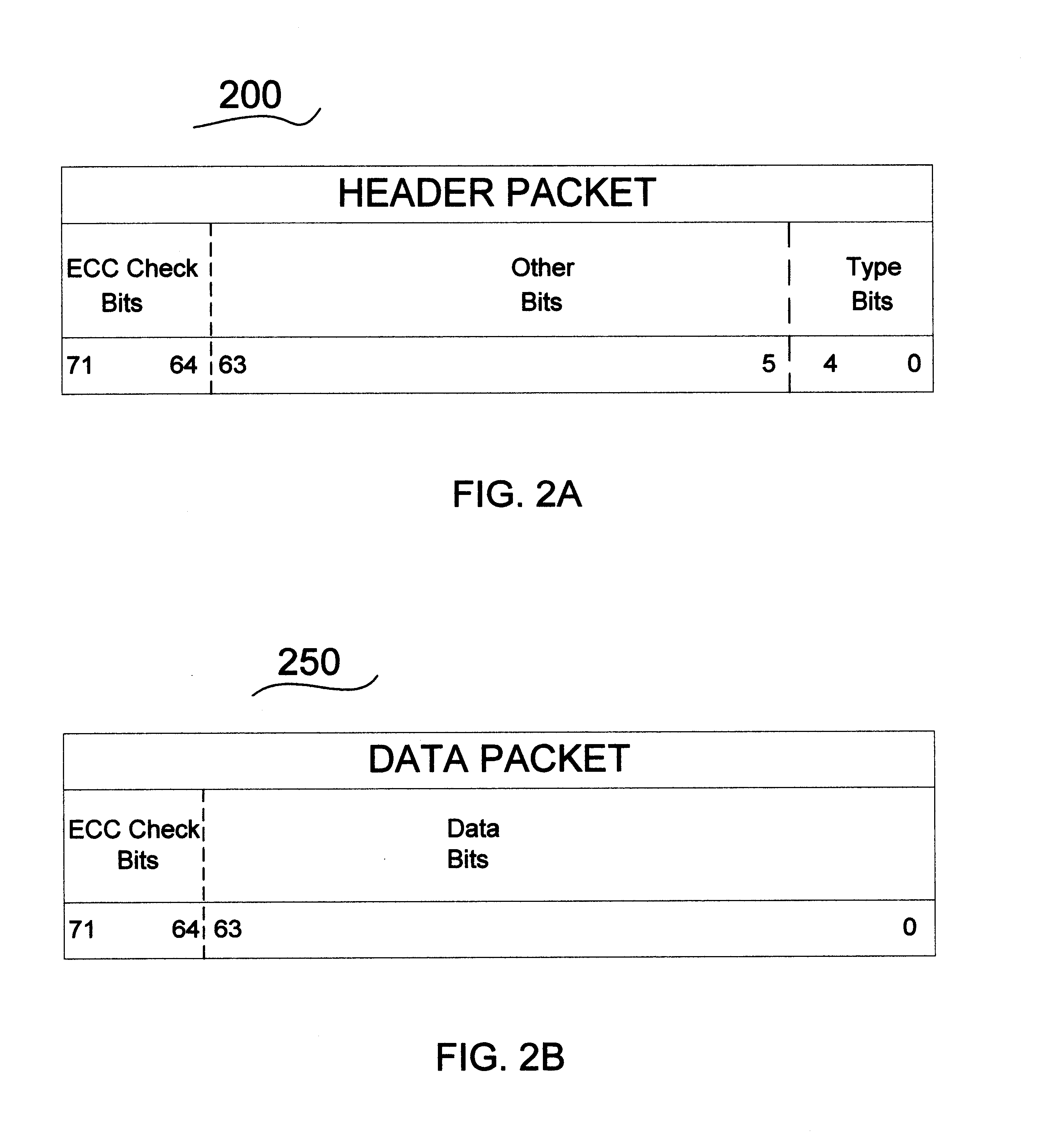
In one preferred embodiment of the invention, a transaction is made up of one header packet by itself, or a header packet followed by or one or more data packets. The packets in a transaction are sent on consecutive clock cycles. A special type of header packet known as an idle packet is sent if there are no transactions available to be sent.

This preferred embodiment of the invention also includes a special synchronizing sequence, which is made up of two new types of header packets. The first of the new header packet types is called a drop-me warning packet. The second of the new header packet types is called a drop-me packet. The synchronizing sequence consists of a series of drop-me warning packets followed by a series of drop-me packets. The transmitting chip periodically sends a synchronizing sequence betwe...


PUM


Abstract

An apparatus and method for an improved asynchronous communication channel between a transmitter and a receiver having separate clocks. The invention provides a simple implementation that solves both the overflow and the underflow problem using the same mechanism, and reduces complexity by elimination of the control split between the two clock domains. A first embodiment of the invention is a method for preventing packet underflow and packet overflow for packets sent across an asynchronous link between a transmitter and a receiver, including a buffer that can store a number of packets greater than an ideal number of packets. The method includes sending a predetermined number of drop-me warning packets and sending one or more drop-me packets from the transmitter to the receiver, receiving the predetermined number of drop-me warning packets and the one or more drop-me packets in the buffer, compensating for packet overflow when the number of packets is greater than the ideal number of packets in the buffer by skipping at least one drop-me packet, and compensating for packet underflow in the buffer when the number of packets is less than the ideal number of packets by stalling access to the buffer for one or more clock cycles. A second embodiment of the invention is an asynchronous link for packets sent between a transmitter having a first clock and a receiver having a second clock, including a buffer to receive the first clock from the transmitter and receive from the transmitter a number of packets equal to or different to a predetermined ideal number of packets, a write pointer, and a read pointer, and a read pointer control circuit to change the read pointer, wherein the buffer can receive drop-me packets, and the read pointer can skip a drop-me packet in the buffer.

Description

1. Field of the InventionThis invention relates generally to an improvement in asynchronous communication, and more specifically to preventing packet underflow and overflow without undue circuit complexity.2. Description of the Prior ArtIn a system with multiple integrated circuit (IC) chips operating at different core frequencies, if the transmitting chip clock frequency is different from the receiving chip clock frequency, there may be packet overflow or underflow problems. A packet overflow problem occurs when the transmitting chip clock frequency is higher than the receiving chip clock frequency, and some packets are dropped at the receiving chip. A packet underflow problem occurs when the transmitting chip clock frequency is lower than the receiving chip clock frequency, and the receiving chip has some clock cycles when there are no valid data packets from the transmitting chip. These packet underflow episodes are sometimes referred to as bubbles.One prior art solution involves...

Claims


Application Information

Patent Timeline
IPC IPC(8): G06F13/38H04L7/04
CPCG06F13/387H04L7/005H04L2007/045
Inventor SHARMA, DEBENDRA DASWILLIAMSON, DONALD A.JACOBS, EDWARD M.
Owner VALTRUS INNOVATIONS LTD
Learn More