
Actuator

a technology of actuators and actuators, applied in the field of actuators, can solve the problems of slow response in temperature control, large force required to drive the movable member, and limit the reduction of the weight of the actuator using electromagnetic motors, and achieve the effect of large displacement and good respons

Inactive Publication Date: 2004-10-12
HONDA MOTOR CO LTD
View PDF4 Cites 10 Cited by
  • Summary
  • Abstract
  • Description
  • Claims
  • Application Information

AI Technical Summary

Benefits of technology

The present invention provides an actuator that can generate large displacement and force with good response when a small magnetic field is applied. The actuator uses a magnetic, resilient, shape memory member that is reoriented by a stress generated by the magnetic field. The actuator can be driven by depositing the magnetic shape memory member in a slanting magnetic field generated from a magnetic field generator. The actuator can be used in various applications, such as in the field of robotics, where precise control of movement is important.

Problems solved by technology

However, because the output densities of the electromagnetic motors depend on the weight of motors, there are limitations in the reduction of weight in the actuators using electromagnetic motors.
However, when the spring has a large repulsive force, a large force is required to drive the movable member against the spring force.
However, a shape memory phenomenon by temperature change requires heating and cooling, and heat diffusion particularly at the time of cooling is rate-determining, resulting in slow response in the temperature control.

Method used


Image

  • Actuator
  • Actuator
  • Actuator

Examples


example 2

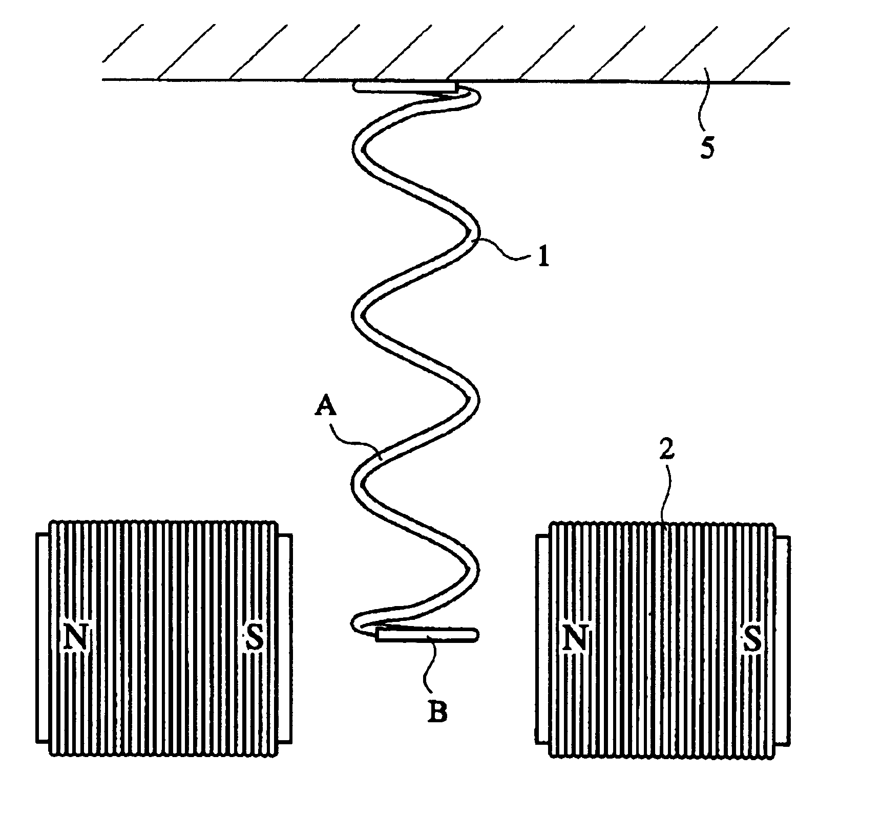
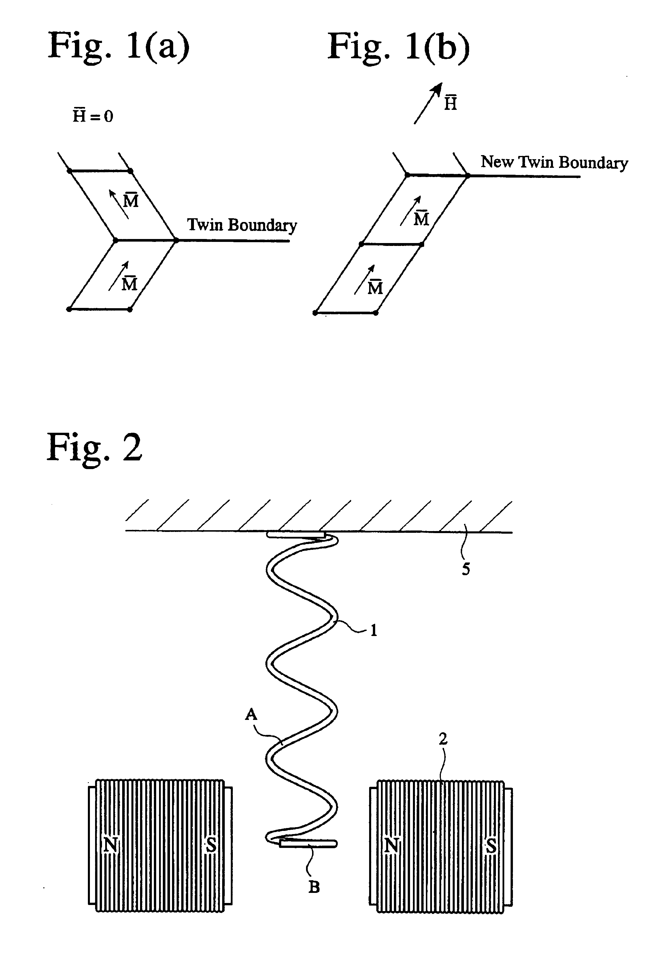
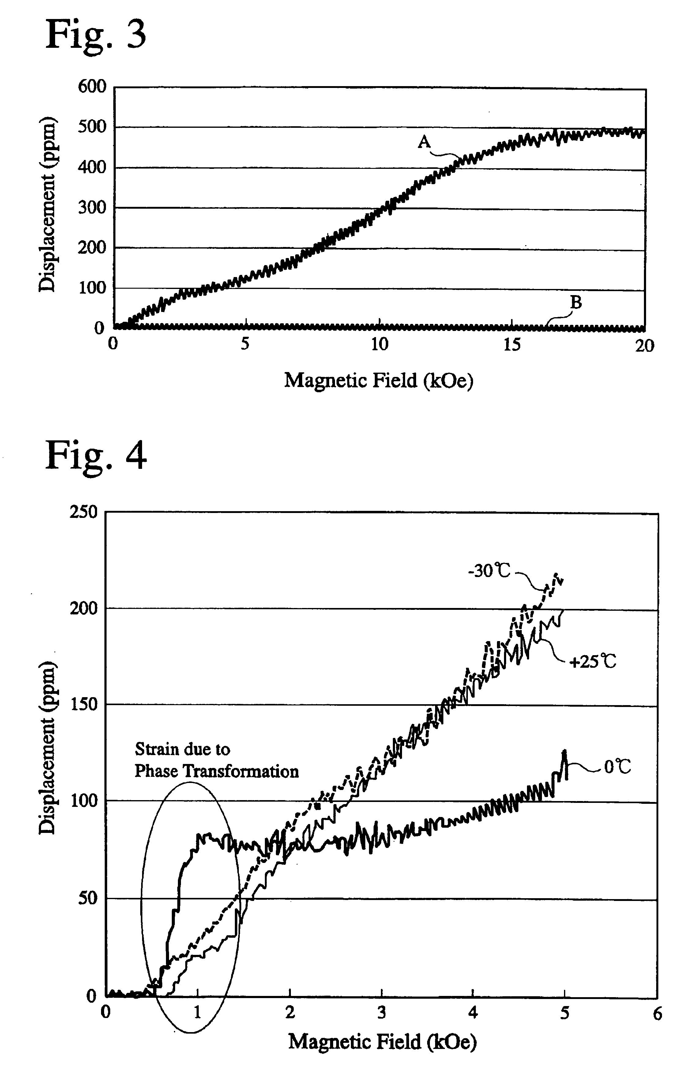
Two magnetic shape memory coil springs were produced in the same manner as in Example 1. Also, a cylindrical electromagnetic coil 2 of 13 mm in outer diameter, 5 mm in length and 2 nm in thickness was produced by winding a wire having a diameter of 0.5 mm around a bobbin. A first magnetic shape memory coil spring 1 was penetrated into one electromagnetic coil 2, which was positioned at a center of the magnetic shape memory coil spring 1, to provide an actuator A. A second magnetic shape memory coil spring 1 was penetrated into two electromagnetic coils 2, which were positioned at both ends of the magnetic shape memory coil spring 1, to provide an actuator B. In both cases, a gap between the electromagnetic coil 2 and the magnetic shape memory coil spring 1 was 1 mm.

Measurement was conducted on the gradient of a magnetic field generated when the electromagnetic coils 2 of the actuators A and B were energized. FIG. 10(a) shows a profile of the magnetic field gradient in the actuator A...


PUM

PropertyMeasurementUnit
temperatureaaaaaaaaaa

Abstract

An actuator comprising a magnetic, resilient, shape memory member formed by a substance having a twin structure, and a magnetic field generator, at least part of the magnetic, resilient, shape memory member being disposed in a gradient magnetic field generated from the magnetic field generator such that the twin structure is reoriented by the magnetic field, whereby the shape memory resilient member is driven.

Description

The present invention relates to an actuator comprising a magnetic shape memory alloy member such as a spring, etc., which can be driven in a relatively small magnetic field, thereby giving large stroke and output force.In the technical fields of robots, machine tools, automobiles, etc. utilizing electromagnetic motors, driving systems are required to have reduced weight. However, because the output densities of the electromagnetic motors depend on the weight of motors, there are limitations in the reduction of weight in the actuators using electromagnetic motors. Accordingly, demand is mounting on actuators providing large outputs with reduced size and weight.Conditions required for the actuators are that a movable member is displaced to a desired position when driven, and returns to an original position without fail while idling, and that a large output is obtained to drive the movable member even though there is a large load. In order that the movable member returns to an origina...

Claims


Application Information

Patent Timeline
Patent Type & Authority Patents(United States)
IPC IPC(8): H01L41/00H01L41/12H10N35/00
CPCH01L41/12H10N35/00
Inventor OHTA, MASAHIROSUKIGARA, TORU
Owner HONDA MOTOR CO LTD
Learn More