
Flash control device, electronic flash device, and photographing system

a flash control device and electronic flash technology, applied in the field of electronic flash devices, can solve the problems of consuming more power for fp flashes than discrete flashes, and obtaining a proper photographing condition for fp flashes is more complicated than discrete flashes

Inactive Publication Date: 2004-10-05
NIKON CORP
View PDF3 Cites 14 Cited by
  • Summary
  • Abstract
  • Description
  • Claims
  • Application Information

AI Technical Summary

Benefits of technology

Another object of the present invention is to provide a flash control device that properly switches the flash mode between the discrete flash mode and the FP flash mode and sets a photographing condition for setting a proper exposure amount, thereby eliminating the user's trouble in caring about the setting of the flash mode.
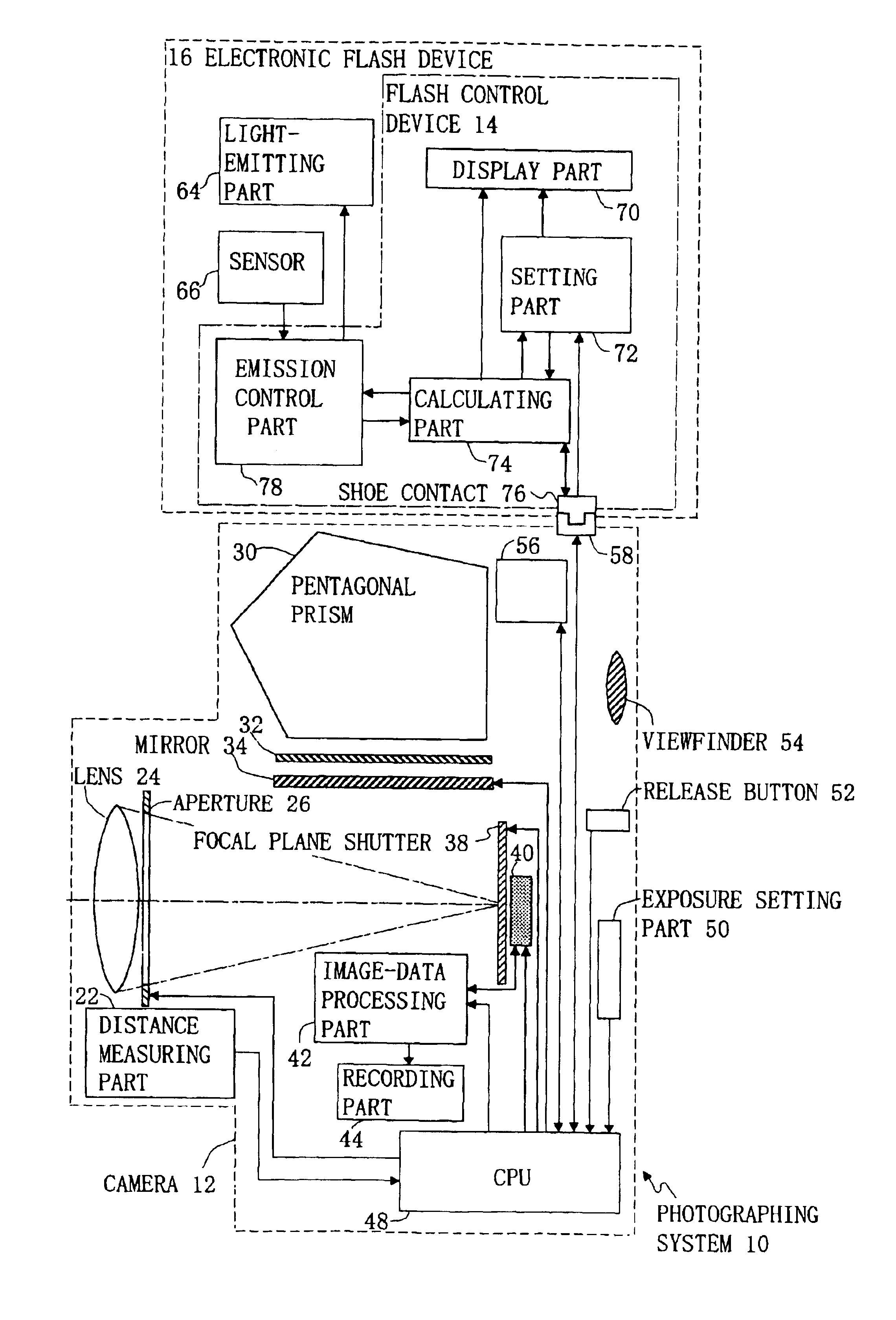
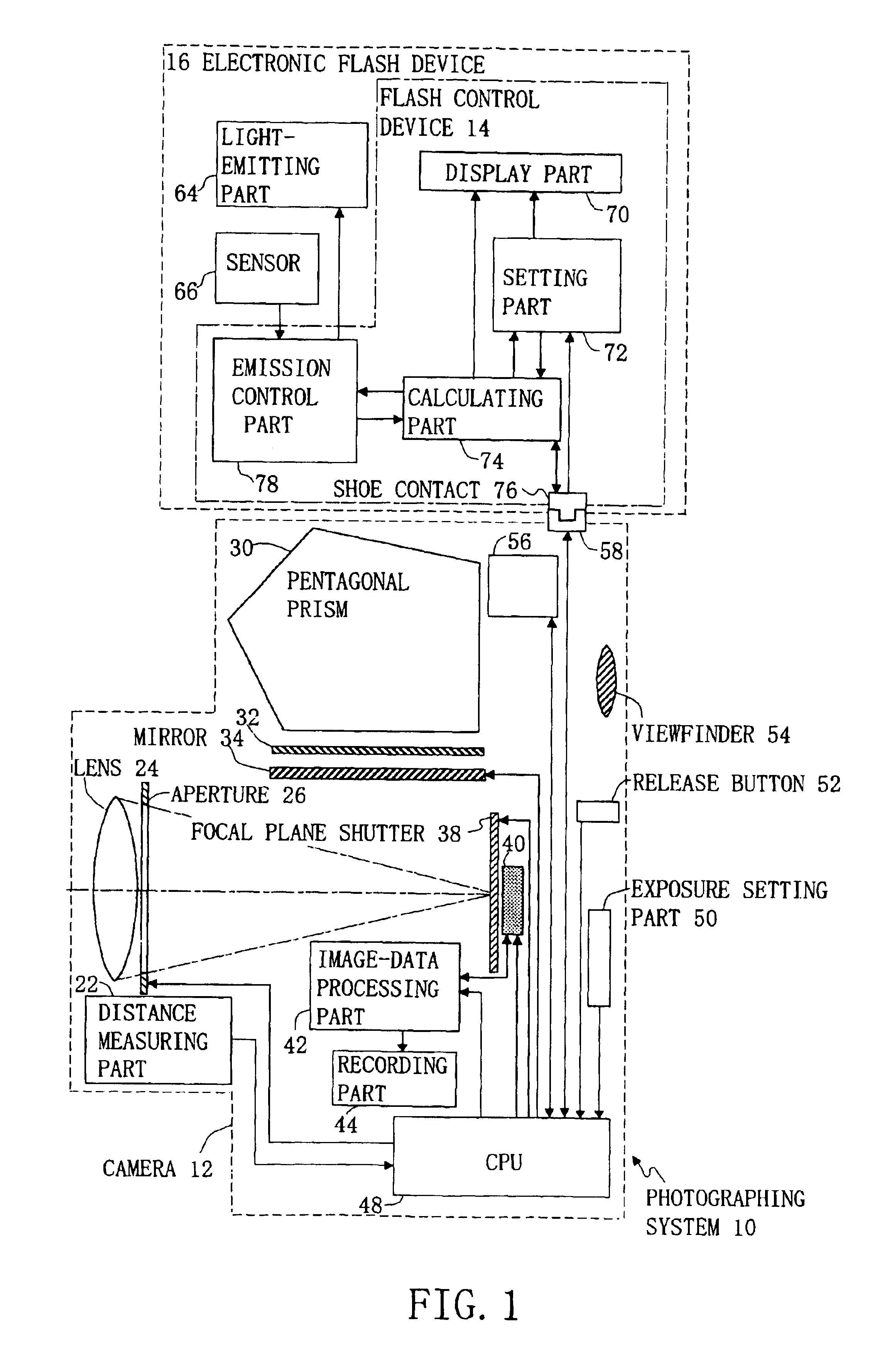
A photographing system of the present invention has an electronic flash device that has a flash control device and a light-emitting part and that has switchable flash modes of the discrete flash mode and the FP flash mode, and a camera having an image pickup part that picks up an image of an object. The image pickup part comprises, for example, a lens, an aperture, a shutter, and an image pickup device. The flash control device comprises a distance input part for inputting an object distance, a calculating part, and an emission control part. When the electronic flash device is in the FP flash mode, the calculating part calculates a proper flash intensity according to the object distance and an f-number, a sensitivity, and an exposure time of a camera. The proper flash intensity refers to a degree of intensity necessary for illuminating an object with a proper light amount. When the electronic flash device is in the discrete flash mode, the calculating part calculates the proper flash intensity according to the object distance, the f-number, and the sensitivity. The emission control part instructs the electronic flash device to flash with the proper flash intensity. The flash control device performs flash control so as to illuminate the object with a proper exposure amount. Thus, the photographic system of the present invention may realize an effect that even beginner-level users who are not familiar with the settings of the flash modes as the discrete flash mode or FP flash mode can easily set a proper flash intensity for setting a proper exposure amount.

Problems solved by technology

Thus, the FP flash consumes much power than the discrete flash.
In other words, obtaining a proper photographing condition in the FP flash is more complicated than that in the discrete flash because the FP flash requires one more parameters than the discrete flash.

Method used


Image

  • Flash control device, electronic flash device, and photographing system
  • Flash control device, electronic flash device, and photographing system
  • Flash control device, electronic flash device, and photographing system

Examples


Embodiment Construction

>

In the conventional electronic flash device the user has to select a flash intensity, and it automatically sets the discrete flash mode or the FP flash mode according to an exposure time, and displays a proper object distance according to the selected flash intensity. Therefore, the automatic flash mode switching occurring with a variance in the exposure time due to a variance in the luminance of the object changes the proper object distance for display.

In contrast, in the electronic flash device according to the present embodiment the user is the one to input an object distance, and it automatically sets the discrete flash mode or the FP flash mode according to an exposure time calculated in the camera side, and calculates a proper flash intensity in the set flash mode according to the input object distance and the exposure time, the f-number, and the sensitivity calculated in the camera side. Because of this, even beginner-level users who are not familiar with the settings of the...


PUM


Abstract

A flash control device comprises a distance input part, a calculating part, and an emission control part. When an electronic flash device is in an FP flash mode, the calculating part calculates a proper flash intensity according to an object distance, an f-number, and sensitivity, the f-number and the sensitivity of a camera. When the electronic flash device is in a discrete flash mode, the calculating part calculates a proper flash intensity according to an object distance, an f-number, and the sensitivity. The emission control part instructs the electronic flash device to flash with a proper flash intensity. The flash control device controls flashing so that the object is illuminated with a proper exposure amount.

Description

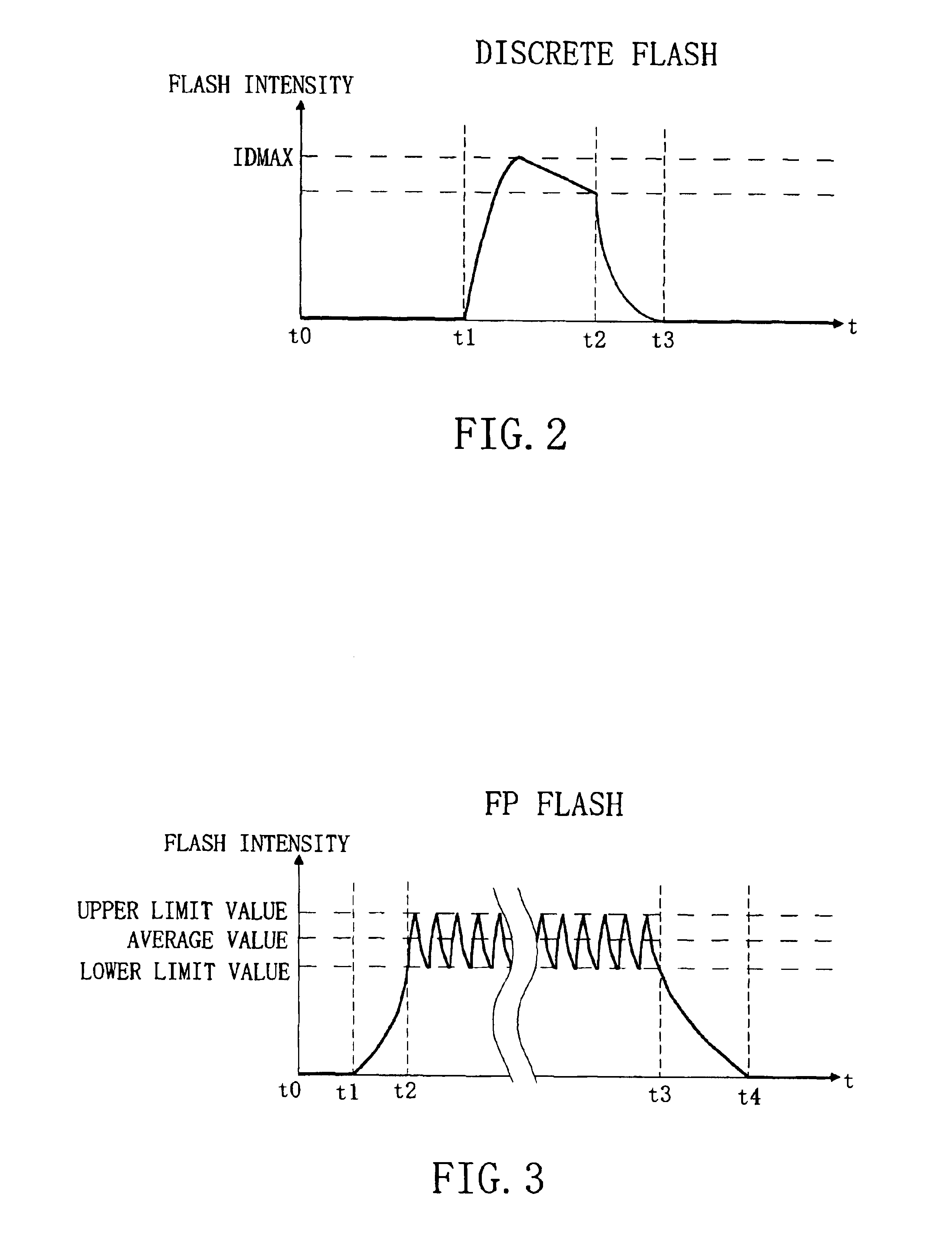
This application is based upon and claims the benefit of priority from the prior Japanese Patent Application No. 2002-246684, filed on Aug. 27, 2002, the entire contents of which are incorporated herein by reference.1. Field of the InventionThe present invention relates to an electronic flash device for use with a camera, in particular, to a control device for use with an electronic flash device. In addition, the present invention relates to a photographing system having an electronic flash device and a camera.2. Description of the Related ArtA discrete flash and an FP flash are known as flash systems of electronic flash devices for use with cameras. The discrete flash system flashes immediately after a shutter curtain is fully opened. On the other hand, the FP flash system repeatedly flashes, during the entire slit exposure with a shutter curtain not fully opened, at time intervals as the flashes are recognizable as flat light. The flash duration of the FP flash is longer than that...

Claims


Application Information

Patent Timeline
Patent Type & Authority Patents(United States)
IPC IPC(8): G03B7/16H05B41/30H05B41/32G03B15/05
CPCH05B41/325G03B7/16G03B7/17
Inventor TAKEUCHI, HIROSHI
Owner NIKON CORP
Learn More