
Cleaning device

A technology of cleaning device and adsorption device, which is applied in cleaning equipment, cleaning machinery, carpet cleaning, etc., can solve the problems of not being able to scrape off, cleaning is not clean, cleaning is not clean, etc., and achieve the effect of eliminating trouble and trouble

Inactive Publication Date: 2013-03-06
徐 尧山
View PDF0 Cites 23 Cited by
  • Summary
  • Abstract
  • Description
  • Claims
  • Application Information

AI Technical Summary

Problems solved by technology

[0004] However, in addition, because today is a highly commercialized society, especially in the city, there are many buildings, high-rise buildings can be seen everywhere, and the most troublesome cleaning of the building is the cleaning of the curtain or glass of the building, because the curtain of the building is clean. The cost is high, and the cleaning is not clean, which often causes disputes. The main dispute is of course that the cleaning is not clean, because the curtain of the building is cleaned from top to bottom, and the crane and the cleaners on the crane are used to move from top to bottom And go down to clean one by one, and when cleaning, you must first mix water and detergent and spray it on the glass curtain, then use a brush to scrub hard, and finally use a rubber scraper to scrape off the residual sewage or dirt on the glass window or glass curtain. so as to achieve cleanliness;
[0005] And because water and detergent must be sprayed on the glass curtain first, the sewage will flow downward, but also because the sewage will flow downward, it is easy for sewage or dirt to get stuck in every corner and cannot be scraped off. Or, the glass curtains on the lower floor will be dirtier due to sewage and dirt, and it will be more difficult to clean

Method used


Image

  • Cleaning device
  • Cleaning device
  • Cleaning device

Examples


Embodiment Construction

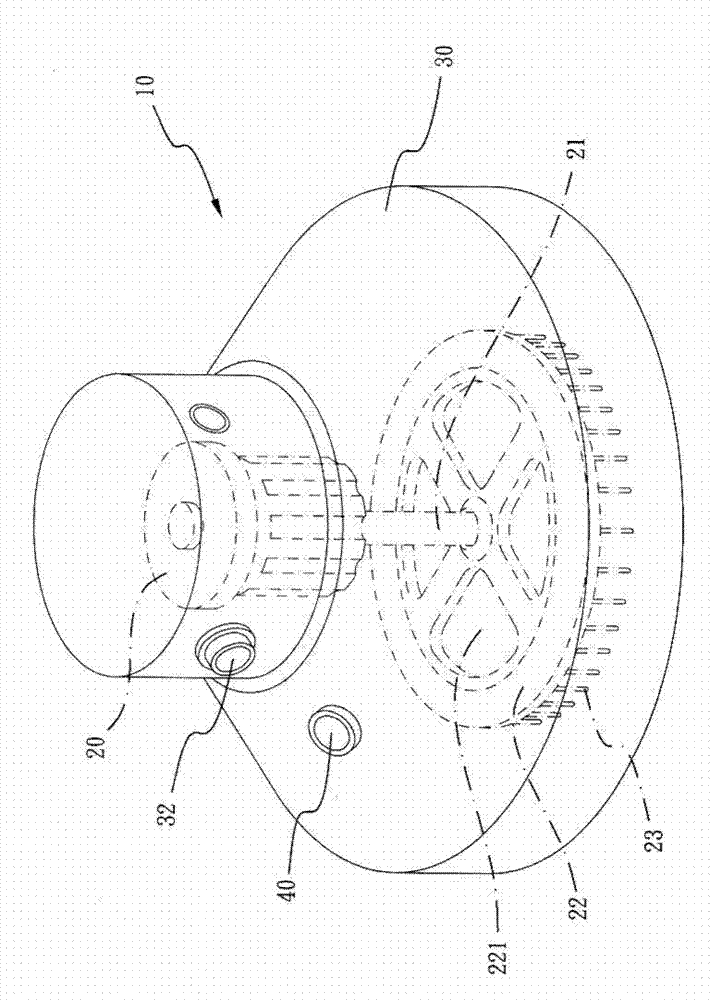
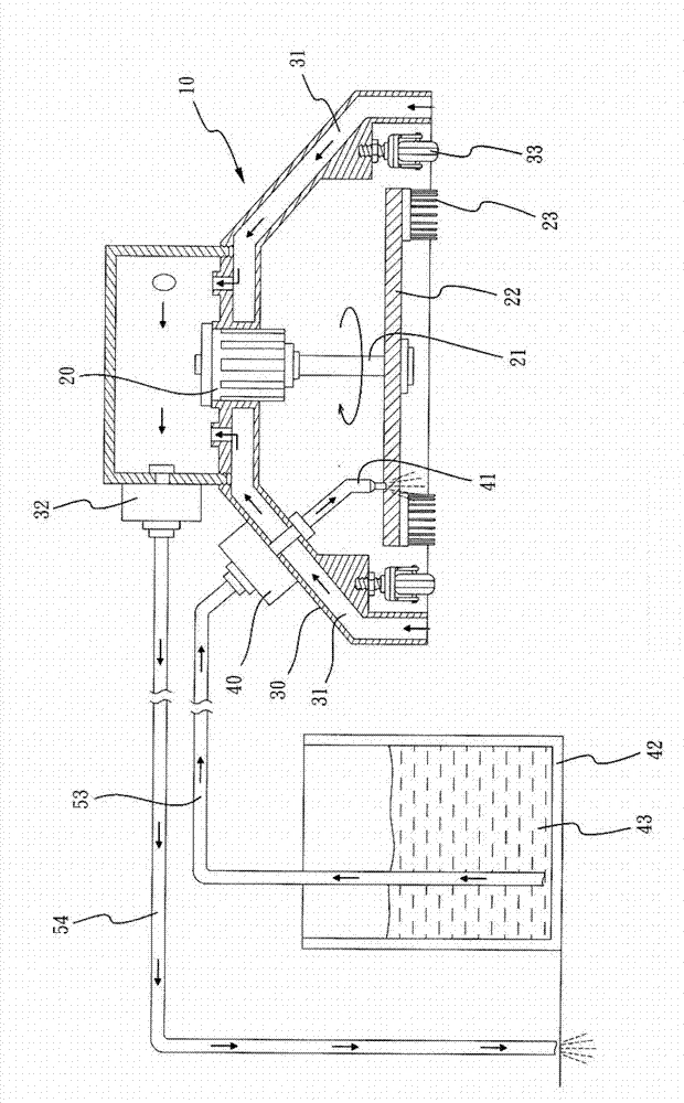
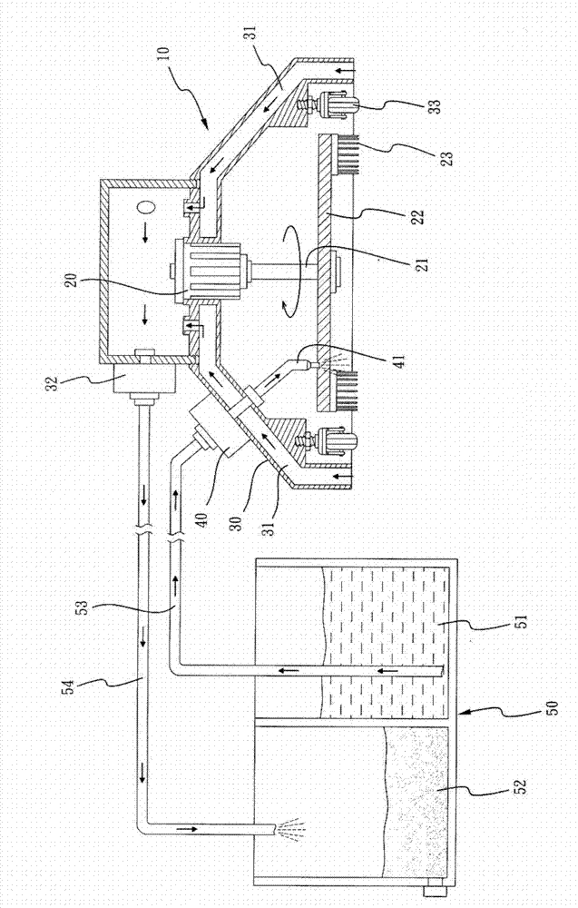
[0039] The present invention relates to a cleaning device, such as Figure 1 to Figure 2 As shown, the device includes a body 10, a drive motor 20 is arranged in the body 10, and the drive motor 20 can drive a shaft 21, and the shaft 21 is connected to an annular brush body 22, and the bottom of the annular brush body 22 is And be provided with several bristles 23, and make when drive motor 20 drives, can rotate axle bar 21, and then rotate annular brush body 22, and make the bristle 23 of annular brush body 22 can be used for scrubbing floor or glass;

[0040] In addition, a cover 30 is provided on the outer periphery of the main body 10, and a hollow adsorption ring groove 31 is formed on the inner periphery of the cover body 30, and the adsorption ring groove 31 is connected to the inside of the main body 10;

[0041] And 10 is provided with a negative pressure adsorption device 32 in the main body, and this negative pressure adsorption device 32 can make use of its negativ...


PUM


Abstract

The invention provides a cleaning device. The cleaning device comprises a body in which a driving motor is arranged; the driving motor is assembled with a shaft lever which is connected with an annular brush body; a plurality of hairs are placed at the bottom of the annular brush body; once the driving motor acts, the shaft lever can be rotated, and then the annular bush body can be rotated; moreover, a cover body is arranged at the periphery of the body; a hollow absorbing ring slot is formed in the cover body; the body is connected with a negative pressure absorbing device which can be used for generating absorbing force in the absorbing ring slot; at least one movable wheel body is also arranged on the side of the bottom end of the cover body; a pressure pump ejecting device with a water ejecting part is arranged on the body; the pressure pump ejecting device is provided with a containing groove in a matching manner; a cleaning agent formed by mixing clean water with a detergent is stored in the containing groove; and the cleaning agent in the containing groove communicated with the pressure pump ejecting device is ejected into the annular brush body by the water ejecting part. By adopting the cleaning device, the practical effects of quick cleaning and automatic cleaning can be realized.

Description

technical field [0001] The invention relates to a cleaning device, in particular to a cleaning device which is simple, fast and practical for users. Background technique [0002] As we all know, the biggest headache for housewives is the cleaning of the home, and these cleanings are especially difficult to clean the glass, the floor and other places, because the floor and the glass must be cleaned by mixing water and detergent into a detergent, and then use rubber to clean them. Wiping the glass or the floor with a scraper or a mop is quite troublesome, especially when drying the scrubbed sewage, because housewives need to constantly absorb and dehydrate water, and even change the water , which can be said to be a great trouble and burden for housewives; [0003] Even though the [Good God Mop] mop, which is very popular nowadays, is only more convenient for dehydration in use, it still needs to absorb water and change water. Moreover, it is quite hard to wipe a large area o...

Claims


Application Information

Patent Timeline
IPC IPC(8): A47L11/283A47L1/02
Inventor 徐尧山
Owner 徐 尧山
Learn More