System and method for facilitating welding system diagnostics
What is Al technical title?
Al technical title is built by PatSnap Al team. It summarizes the technical point description of the patent document.
a welding system and diagnostic technology, applied in the field of system and method for facilitating welding diagnostics, can solve the problems of increasing difficulty in controlling, maintaining, servicing and supplying multiple and isolated locations in large centers, increasing down time, and increasing complexity
Inactive Publication Date: 2004-09-21
LINCOLN GLOBAL INC
View PDF12 Cites 129 Cited by
Summary
Abstract
Description
Claims
Application Information
AI Technical Summary
This helps you quickly interpret patents by identifying the three key elements:
Problems solved by technology
Method used
Benefits of technology
Yet another aspect of the present invention provides for the expert component to access an expert data store, a local service support data store, a remote expert data store and / or a remote service support data store to facilitate welding diagnostics. The expert data store and / or the remote expert data store can store information associated with welding diagnostics (e.g., current expert system rules, diagrams, welder troubleshooting procedure(s) and / or welder software upgrade(s)) that the expert component can utilize to facilitate welding diagnostics. The local service support data store and / or the remote service support data store can store information (e.g., welder service record, welder part order information, welder warranty information and / or welder service information) that the expert component can utilize to facilitate welding diagnostics.
Problems solved by technology
Given the nature and requirements of modern and more complex manufacturing operations however, welding systems designers, architects and suppliers face increasing challenges in regard to upgrading, maintaining, controlling, servicing and supplying various welding locations.
Unfortunately, many conventional welding systems operate in individually controlled and somewhat isolated manufacturing locations in regard to the overall assembly process.
Thus, controlling, maintaining, servicing and supplying multiple and isolated locations in large centers, and / or across the globe, has become more challenging, time consuming and expensive.
One such challenge relates to facilitating service support of welder(s) and / or welding system(s).
Conventionally, service support of welder(s) has occurred via an awkward combination of technical manuals and / or bulletins from manufacturers and / or diagnosis of welder(s) by operator(s).
As welder(s) become increasing complex they have likewise become increasing difficult to service and / or support leading to increase down time.
Further, welder fault(s) and / or alarm(s) have been difficult for operator(s) to monitor and / or initiate corrective action.
This can be time-consuming and can lead to inconsistent result based upon an operator's level of experience.
Method used
Image
Click on the blue label to locate the original text in one second.
Reading with bidirectional positioning of images and text.
Examples
Embodiment Construction
The present invention is now described with reference to the drawings, wherein like reference numerals are used to refer to like elements throughout. In the following description, for purposes of explanation, numerous specific details are set forth in order to provide a thorough understanding of the present invention. It may be evident to one skilled in the art that the present invention may be practiced without these specific details. In other instances, well-known structures and devices are shown in block diagram form in order to facilitate description of the present invention.
As used in this application, "system" is a structure comprising one or more components. A "component" is a structure comprising computer hardware and / or software. For example, a component can be, but is not limited to, a computer readable memory encoded with software instructions or a computer configured to carry out specified tasks. By way of illustration, both an application program stored in computer read...
PUM
Property
Measurement
Unit
voltage meter
aaaaa
aaaaa
current meter
aaaaa
aaaaa
current
aaaaa
aaaaa
Abstract
A system and method for facilitating welding system diagnostics is provided. The invention includes a welder, a local system, a remote system, and / or an alarm component. The invention further provides for receiving sensor input(s), performing test sequence(s) based, at least in part, upon the sensor input(s) and / or performing internal diagnostics. The invention further provides for determining a health status of the welder and communicating the health status of the welder to the local system, the remote system and / or the alarm component. The health status of the welder can include welder alarm(s) and / or fault(s). Information regarding the health status of the welder can be sent by telephone, voicemail, e-mail and / or beeper. The welder can communicate with the local system and / or remote system to schedule maintenance. The invention further provides for a expert component to facilitate welding diagnostics based, at least in part, upon the health status of the welder, welder data, an expert data store, a local service support data store, a remote expert data store and / or a remote service support data store. The expert component can employ various artificial intelligence technique(s) (e.g., Bayesian model, probability tree network, fuzzy logic and / or neural network) to facilitate welding diagnostics based, at least in part, upon the health status received from the welder. The expert component can adaptively modify its modeling technique(s) based upon historical success (e.g., learn from success of previous welding diagnostics). The invention further provides for the welder, local system and / or remote system to initiate corrective action, at least temporarily, based, at least in part, upon the health status of the welder.
Description
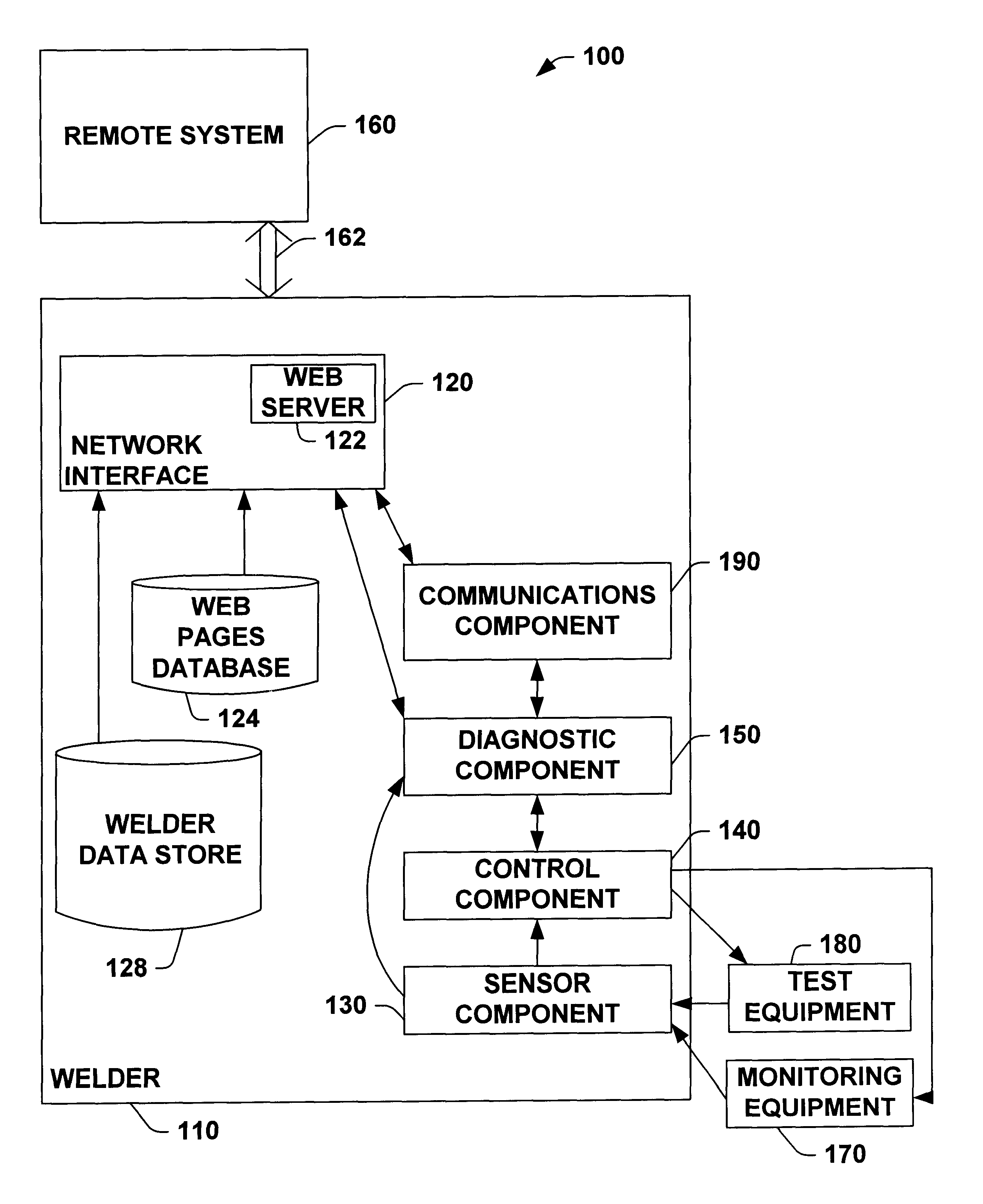
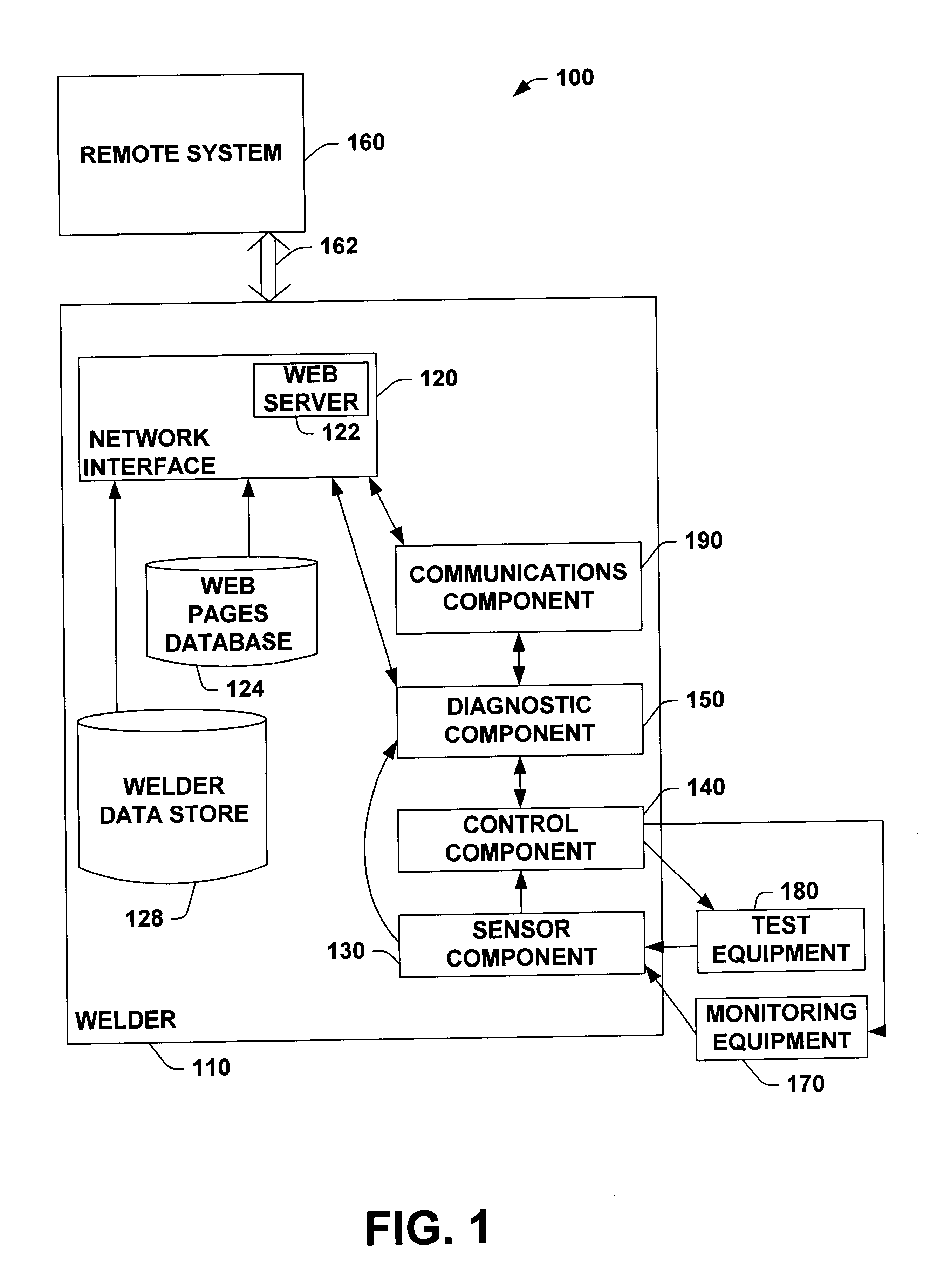
The present invention relates generally to computer and welding systems. More particularly, the present invention relates to a system and method for facilitating welding system diagnostics.Welding systems reside at the core of the modern industrial age. From massive automobile assembly operations to automated manufacturing environments, these systems facilitate joining in ever more complicated manufacturing operations. One such example of a welding system includes an electric arc welding system. This may involve movement of a consumable electrode, for example, toward a work piece while current is passed through the electrode and across an arc developed between the electrode and the work piece. The electrode may be a non-consumable or consumable type, wherein portions of the electrode may be melted and deposited on the work piece. Often, hundreds or perhaps thousands of welders are employed to drive multiple aspects of an assembly process, wherein sophisticated controllers enable ind...
Claims
Application Information
Patent Timeline
Application Date:The date an application was filed.
Publication Date:The date a patent or application was officially published.
First Publication Date:The earliest publication date of a patent with the same application number.
Issue Date:Publication date of the patent grant document.
PCT Entry Date:The Entry date of PCT National Phase.
Estimated Expiry Date:The statutory expiry date of a patent right according to the Patent Law, and it is the longest term of protection that the patent right can achieve without the termination of the patent right due to other reasons(Term extension factor has been taken into account ).
Invalid Date:Actual expiry date is based on effective date or publication date of legal transaction data of invalid patent.