
Power source unit

a technology of power source unit and power supply, which is applied in the direction of machine/engine, process and machine control, electric generator control, etc., can solve the problems of dc-dc converter 106, cost increase, and cost increas

Inactive Publication Date: 2004-09-21
TOYOTA JIDOSHA KK
View PDF6 Cites 27 Cited by
  • Summary
  • Abstract
  • Description
  • Claims
  • Application Information

AI Technical Summary

Benefits of technology

The invention relates to a power source unit for vehicles that uses multiple chargeable / dischargeable batteries. The unit includes an inverter, a first battery, and a second battery. The second battery has a lower voltage than the first battery. The power source unit also includes a power conversion device and a switching device that switches between the first and second batteries for charging and discharging. The invention aims to provide a power source unit that allows charging and discharging of the batteries at low costs. The technical effect of the invention is to reduce the cost of parts and to allow for selective charging and discharging of the batteries without the need for a step-up circuit. The invention also includes a coil that can function as a step-up chopper to allow power transfer between the batteries.

Problems solved by technology

This may result in the cost increase.
The resultant configuration of the DC-DC converter 106, thus, becomes complicated, increasing the cost.

Method used


Image

  • Power source unit
  • Power source unit
  • Power source unit

Examples


first embodiment

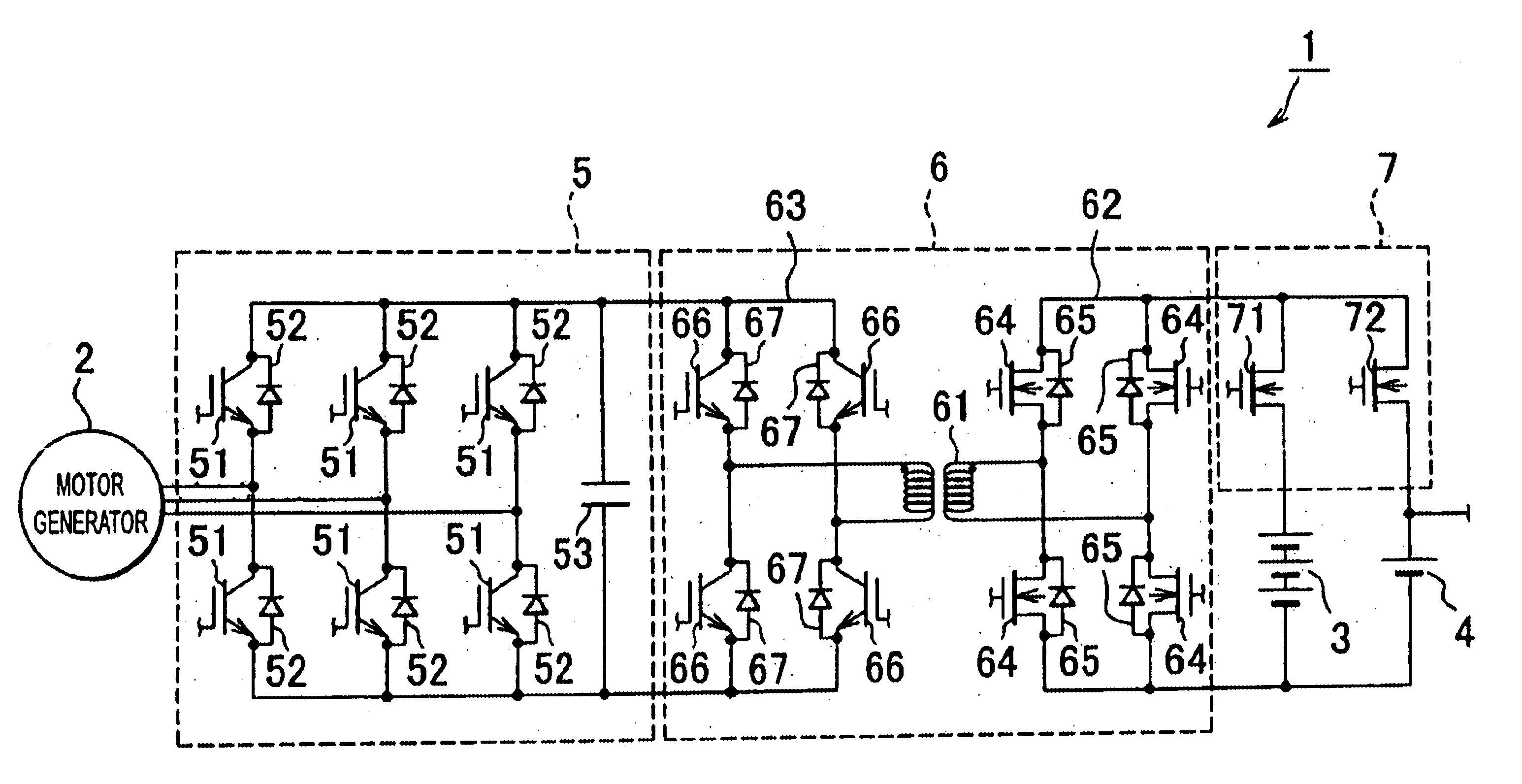
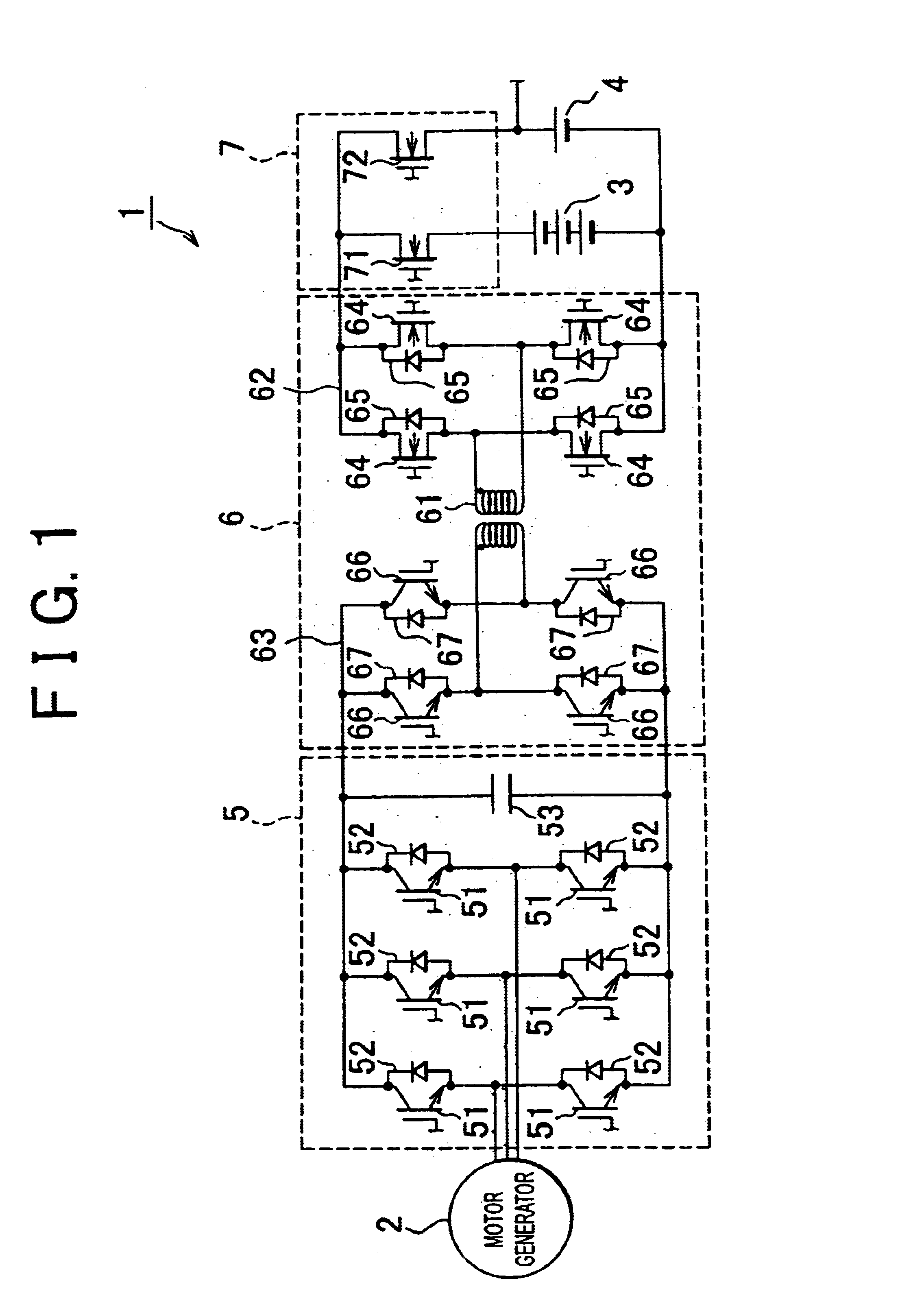
FIG. 1 is an exemplary schematic view of a power source unit of a first embodiment. As shown in FIG. 1, a power source unit 1 is mounted on a hybrid vehicle having a combination of an engine and a motor generator 2. The power source unit 1 can be mounted on any type of the hybrid vehicle including a series type in which wheels are driven by a motor generator, and an engine serves to supply power to the motor generator 2, a parallel type in which wheels can be driven by both an engine and a motor generator, or a parallel series type in which functions of both the series type and the parallel type can be obtained.

The power source unit 1 has a main battery 3 and an accessory battery 4. The main battery 3, for example, as a chargeable / dischargeable first battery, mainly serves to supply electricity to the motor generator 2. The main battery 3 is of a higher voltage type, DC 36 to 40 V, for example, compared with the accessory battery 4. The accessory battery 4, for example, as a chargea...

second embodiment

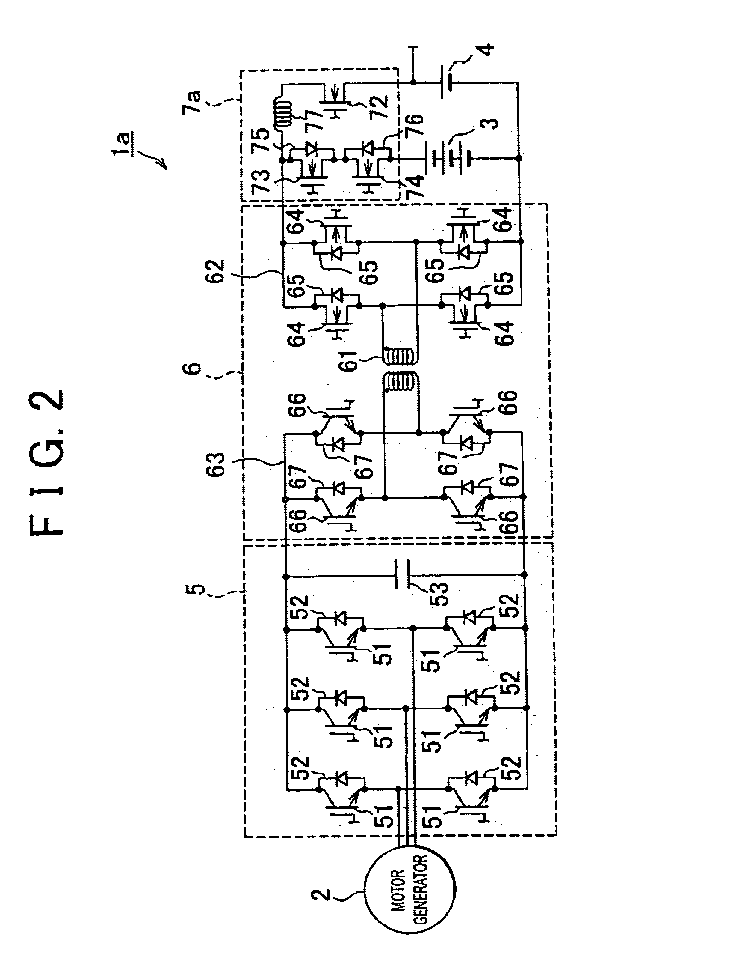
FIG. 2 is an exemplary schematic view of a power source unit according to a second embodiment. As shown in FIG. 2, a power source unit 1a has a similar configuration as that of the power source unit 1 of the first exemplary embodiment. That is, the power source unit 1a has a main battery 3, accessory battery 4, inverter 5, and power converting circuit 6. Like the switching circuit 7 of the first embodiment, a switching circuit 7a of the power source unit 1a serves to switch the connection between the power converting circuit 6 and the main battery 3 and the power converting circuit 6 and the accessory battery 4. The switching circuit 7a and the second bridge circuit 62 constitute the step-up chopper so as to allow power transfer between the main battery 3 and the accessory battery 4.

In the switching circuit 7a, a transistor 73 and a transistor 74 are connected in series between the first bridge circuit 62 and the main battery 3. A coil 77 and the transistor 72 are connected in serie...

first exemplary embodiment

As described above, according to the power source unit 1a relating to this embodiment (in addition to the same operation effects as in the power source unit 1 relating to the first exemplary embodiment) by connecting the coil 77 between the main battery 3 and the auxiliary battery 4 via the switching circuit 7a, it is possible to cause the power converting circuit 6 and the switching circuit 7a to function as step-up and step-down choppers. Therefore, without placing a step-up circuit other than the power converting circuit 6 and the switching circuit 7a, power transfer between the main battery 3 and the auxiliary battery 4 is enabled.

Although a power source unit mounted in a vehicle is explained in the aforementioned embodiments, the power source unit relating to the invention may be adapted to a unit other than one mounted in a vehicle.

As explained above, according to the invention, as a result of enabling a switch of connection between the power converting means and the first and...


PUM

PropertyMeasurementUnit
voltageaaaaaaaaaa
voltageaaaaaaaaaa
voltageaaaaaaaaaa

Abstract

A power source unit includes an inverter connected to a power transfer device, a first battery that can be charged and discharged through the inverter and a second battery that can be charged and discharged through the inverter. The second battery has a power voltage lower than that of the first battery. The power source unit further includes a power conversion device connected to the inverter, providing a transforming function, and a switching device provided between the power conversion device and the first and second batteries. The switching device switches a connection between the power conversion device and the first battery, and the power conversion device and the second battery. The inverter is connected to the first and the second batteries through the power conversion device.

Description

INCORPORATION BY REFERENCEThe disclosure of Japanese Patent Application No. 2001-349130 filed on Nov. 14, 2001 including the specification, drawings and abstract is incorporated herein by reference in its entirety.1. Field of InventionThe invention relates to a power source unit of a vehicle and the like. More particularly, the invention relates to a power source unit in which a plurality of chargeable / dischargeable batteries are provided.2. Description of Related ArtAs a power source unit having a plurality of chargeable / dischargeable batteries, there is a known power source unit, as disclosed in Japanese Patent Application Laid-Open No. 2000-50402, which is mounted in a hybrid vehicle having a combination of an internal combustion engine and a motor. More specifically, as shown in FIG. 5, a power source unit including a high voltage main battery 101 and a low voltage accessory battery 102 causes a motor generator (M / G) 104 to generate electric power by driving an engine 103. The p...

Claims


Application Information

Patent Timeline
Patent Type & Authority Patents(United States)
IPC IPC(8): H02J7/14H02J7/00H02M3/24H02M3/335B60R16/033B60K6/20B60K6/22B60K6/28B60K6/44B60K6/46B60K6/48B60L1/00B60L50/15B60L50/16B60R16/04F02D29/02H02M3/28H02P9/04H02P9/48
CPCB60L11/1868H02J7/1423H02M7/48H02M3/33584Y02T10/7005Y02T10/7066Y10S903/907Y10S903/904B60L58/20Y02T10/70B60L1/00
Inventor TSUJI, KIMITOSHI
Owner TOYOTA JIDOSHA KK
Learn More