
Early/on-time/late gate bit synchronizer

a bit synchronizer and gate gate technology, applied in the field of digital receiver systems, can solve the problems of loss of critical data, often obscured bit synchronization, etc., and achieve the effect of reducing time delays, control logic, and excessive memory buffers

Inactive Publication Date: 2004-09-14
NORTHROP GRUMMAN SYST CORP
View PDF4 Cites 135 Cited by
  • Summary
  • Abstract
  • Description
  • Claims
  • Application Information

AI Technical Summary

Benefits of technology

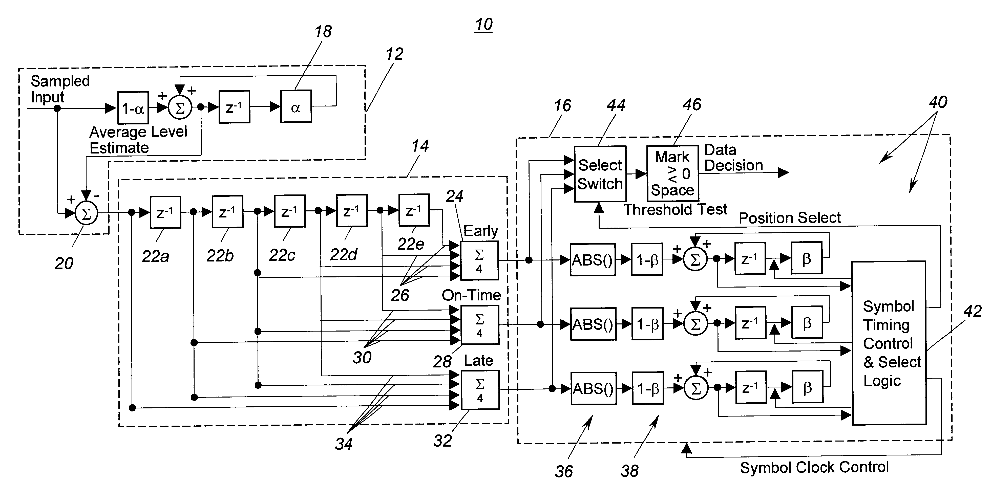
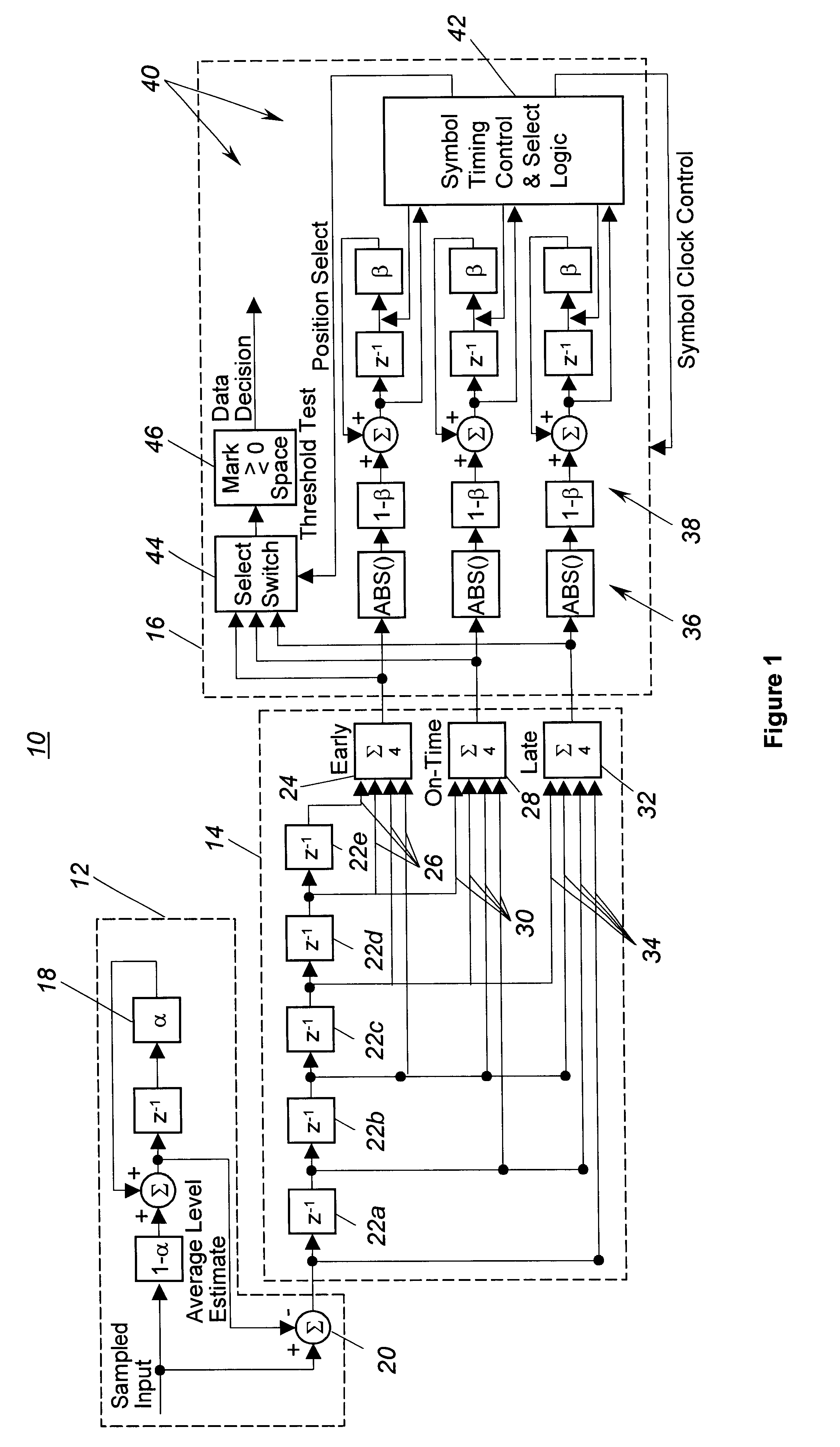
Further in accordance with the present invention, a control module for a bit synchronizer is provided. The control module has an absolute value stage for generating signals that are absolute values of the corresponding timing signals. An integration stage generates integrated signals, where the integrated signals represent the average energy of the corresponding timing signals over a predetermined integration length. The control module further includes a signal selector for generating an output signal by comparing the three integrated signals. The polarity of the timing signal corresponding to the largest integrated signal is used to determine the output bit value. The result is a more efficient digital receiver system that uses relative comparison instead of absolute thresholds for data selection. To maintain correct bit timing, the control module further adjusts the three timing windows by advancing or restarting the windows one sample at a time after each bit decision. The control module therefore eliminates excessive memory buffers, control logic, and time delays.

Problems solved by technology

Bit synchronization is often obscured by received noise, signal fading, relative time drift, and time jitter between the received symbol sequence and the receiver sampling clock.
Depending on the application, losses in bit synchronization can result in losses in critical data.

Method used


Image

  • Early/on-time/late gate bit synchronizer
  • Early/on-time/late gate bit synchronizer
  • Early/on-time/late gate bit synchronizer

Examples


Embodiment Construction

Turning now to FIG. 1, the preferred embodiment of a bit synchronizer 10 in accordance with the present invention is shown in greater detail. While the present invention will be described with respect to input signals commonly used in military applications, it is important to note that the invention is not so limited. Thus, any digital receiver system in which bit synchronization can be obscured by received noise, signal fading, relative time drift, time jitter or any other transmission phenomena can benefit from the present invention.

Generally, the preferred bit synchronizer 10 has a DC level estimator 12, a delay module 14, and a control module 16. The DC level estimator 12 converts a sampled digital signal into a level-adjusted (or antipodal) signal. The delay module 14 generates a first timing signal, a second timing signal, and a third timing signal based on the level-adjusted signal. As will be described in greater detail below, the first timing signal (i.e., early timing sign...


PUM


Abstract

A bit synchronizer for a digital receiver system accounts for loss of bit synchronization due to transmission phenomena. The bit synchronizer includes a DC level estimator for converting a sampled digital signal having a bit rate and a sampling rate into a level-adjusted signal. A delay module generates a first timing signal, a second timing signal, and a third timing signal based on the level-adjusted signal. The timing signals correspond to early, on-time, and late sampling windows. The control module generates an output signal based on the timing signals such that the transmit and receive bit timing are synchronized. In one embodiment, the control module has an absolute value stage, an integration stage, and a signal selector. The signal selector is able to select between the timing signals, adjust the symbol rate to re-center the on-time gate, and memory swap to maintain correct averaging operations.

Description

BACKGROUND OF THE INVENTION1. Field of the InventionThis invention relates generally to digital receiver systems. More particularly, the invention relates to a bit synchronizer for a digital receiver system that synchronizes to the transmitter clock in terms of bit timing in order to extract correct bit information for select receiver processes.2. Discussion of the Related ArtIt is well known that communication systems are a critical part of both commercial and military applications. In fact, as semiconductor technologies advance, the demand for digital communication systems continues to grow. Digital communication systems can be conceptually divided into systems that transmit and systems that receive. In order to meet requirements for faster, more reliable communications associated with the aforementioned demand for digital communication systems, a number of modulation / demodulation schemes have evolved. Two common modulation schemes used in digital systems are amplitude shift keyin...

Claims


Application Information

Patent Timeline
IPC IPC(8): H04L7/033H04L7/02
CPCH04L7/007H04L7/0087
Inventor YUAN, REBECCA W.PAWLOWSKI, PETER R.
Owner NORTHROP GRUMMAN SYST CORP
Learn More