
Capacitively-loaded bent-wire monopole on an artificial magnetic conductor

a technology of artificial magnetic conductor and capacitor, which is applied in the structure of elongated active elements, resonant antennas, radiating elements, etc., can solve the problems of increasing increasing the difficulty of converting amc antennas into handheld devices, and increasing the size of devices, so as to increase the radiation efficiency and battery life of portable devices, reduce the length of antenna elements, and reduce the effect of antenna length

Inactive Publication Date: 2004-07-27
ETENNA
View PDF6 Cites 65 Cited by
  • Summary
  • Abstract
  • Description
  • Claims
  • Application Information

AI Technical Summary

Benefits of technology

"The patent describes an antenna system that can be used in portable devices to improve battery life and increase efficiency. The antenna system includes an artificial magnetic conductor (AMC) and a capacitive load. The capacitive load can be connected to the AMC or a separate metal component. The addition of the capacitive load can reduce the loss of signal between the antenna and a battery or other components in the device. The capacitive load can be a lumped or distributed capacitance, and its effect can be measured in dB. The system can be designed to have a low cost and can be used in various portable devices."

Problems solved by technology

However, one drawback of such an antenna is that the monopole must have an electrical length of one-quarter of a wavelength, which makes integration of the AMC antenna into a handheld device more of a challenge as devices decrease in size.
However, inductors have a number of problems.
One of these problems includes a large amount of loss in the antenna, which results in a relatively inefficient antenna.
The reduction in antenna gain increases the power consumption and decreases the battery life of the device.
In addition, chip inductors are relatively expensive and bulky in comparison with the monopole.
In general, however, the loss when inserting the inductor may be limited to 1-3 dB.
One factor that results in the reduction in efficiency is the windings of the chip inductor, which contribute dissipative loss.
Another factor that degrades the antenna efficiency is the mismatch between the impedance of the antenna and that of the inductor.

Method used


Image

  • Capacitively-loaded bent-wire monopole on an artificial magnetic conductor
  • Capacitively-loaded bent-wire monopole on an artificial magnetic conductor
  • Capacitively-loaded bent-wire monopole on an artificial magnetic conductor

Examples


Embodiment Construction

A separate capacitive load, as opposed to the intrinsic capacitance associated with an artificial magnetic conductor (AMC), may be added to the AMC. Multiple benefits that result include the ability to reduce the antenna element length relative to an unloaded antenna, thereby decreasing the overall size of the antenna. In addition, the radiation efficiency is increased, thereby leading to an increase in battery life for portable devices that use the capacitively loaded antennas. Further, the present invention permits such antennas to be fabricated using high-volume techniques and enable low cost antennas to be produced.

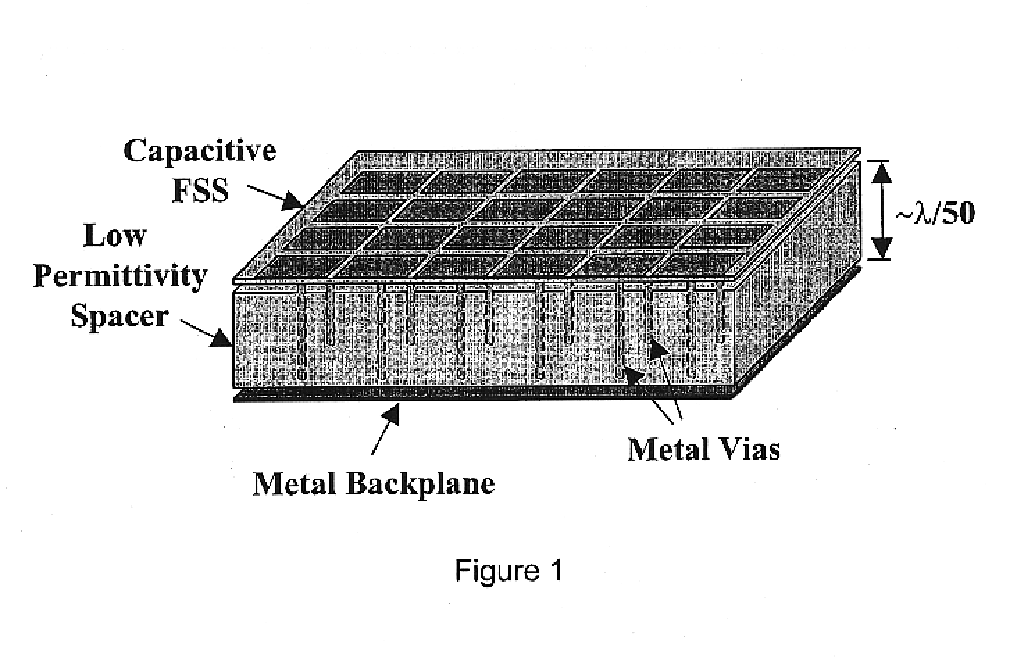
An artificial magnetic conductor (AMC) includes an electrically-thin, periodic structure known as a frequency selective surface (FSS), which may be a printed circuit board. The FSS 202 and 302 may be a multi-layer structure 302, as shown in FIGS. 4(a) and 5(a) or merely a single layer of metal 202 etched on a dielectric layer as shown in FIGS. 4(b) and 5(b). In both t...


PUM


Abstract

An antenna consisting of a thin strip bent-wire monopole disposed on an artificial magnetic conductor (AMC) is loaded at the end opposite to the feed point with a distributed or lumped capacitance to achieve an electrically small antenna for use in handheld wireless devices. The capacitive load reduces the length of the antenna to smaller than one-quarter of a wavelength at a given frequency of operation without suffering a substantial loss of efficiency. This results in an easier integration into portable devices, greater radiation efficiency than other loaded antenna approaches and longer battery life in portable devices, and lower cost than use of a chip inductor.

Description

BACKGROUNDDue to the constant demand for improved efficiency of antennas and increased battery lifetime in portable communication systems high-impedance surfaces have been the subject of increasing research. High-impedance surfaces have a number of properties that make them important for applications in communication equipment. The high-impedance surface is a lossless, reactive surface, whose equivalent surface impedance, ##EQU1##(where E.sub.tan is the tangential electric field and H.sub.tan is tangential magnetic field), approximates an open circuit. The surface impedance inhibits the flow of equivalent tangential electric surface current and thereby approximates a zero tangential magnetic field, H.sub.tan.apprxeq.0.One of the main reasons that high-impedance surfaces are useful is because they offer boundary conditions that permit wire antennas (electric currents) to be well matched and to radiate efficiently when the wires are placed in very close proximity to this surface. Typi...

Claims


Application Information

Patent Timeline
Patent Type & Authority Patents(United States)
IPC IPC(8): H01Q15/00H01Q1/24H01Q9/30H01Q15/14H01Q15/10H01Q9/36H01Q9/42H01Q9/04
CPCH01Q1/243H01Q9/30H01Q9/36H01Q9/42H01Q15/10H01Q15/14H01Q15/008
Inventor LILLY, JAMES D.MCKINZIE, III, WILLIAM E.AUCKLAND, DAVID T.HUMEN, JR., ANDREW
Owner ETENNA
Learn More