Method and apparatus for detecting an object within a dynamic scattering media

a dynamic scattering media and object technology, applied in the field of methods and apparatus for detecting and/or imaging objects, can solve the problems of detectors only being able to detect for a very short period, acoustic imagine suffers from lack of spatial resolution, and the image resolution obtainable using time-of-flight imaging is thus limited

Inactive Publication Date: 2004-06-22
VICTORIA VNIVERSITY OF MANCHESTER THE
View PDF27 Cites 30 Cited by
  • Summary
  • Abstract
  • Description
  • Claims
  • Application Information

AI Technical Summary

Benefits of technology

The invention allows images to be obtained using photons which have travelled optical distances greater than 2 photon transport paths. This is opposite to conventional imaging of dense media, which generally removes or filters out light which has been scattered more than once. Since the invention does not require photons which have undergone ballistic and low order scattering, it is suitable for imaging very dense suspensions where ballistic scattering is limited.
The or each iteration of steps (i) to (v) may be repeated, either sequentially or simultaneously, for additional locations within the media, the results then being combined to construct an image of the object within the media. Where only one wavelength of light is used the image will be two dimensional. However, using two or more different wavelengths as mentioned above (which effectively probe into different depths of the media and / or object, enables the construction of a, three dimensional image.
The media may be modulated to induce, or enhance, dynamic motion within the media to provide or enhance the required dynamic scattering. Similarly, when the object is an object which is at least partially reflective of the or each light wave, the object may be modulated to enhance phase chances in light reflected therefrom.
The or each light wave may be passed through a window prior to entering the media, the window being arranged to reflect light which is detected together with light emerging from the media, thereby producing a heterodyne signal. The window may be adjustably displaced relative to the origin of said light wave to allow control of the intensity of the reflected light which is detected. The window may be arranged to cause the reflected light to undergo multiple reflections before being detected, thereby enabling the path length travelled by the reflected light to be controlled.
An object located within a medium may be caused to modulate to increase the contrast of the phase of scattered light, and thereby improve the resolution of the image.
The window may be arranged to cause the reflected light to undergo multiple reflections before being incident at the detection means, thereby allowing the path length traveled by the reflected light to be controlled.

Problems solved by technology

The shortest measurable distance and the image resolution obtainable using Time of Flight imaging is thus limited by the response time of the detectors used.
A further disadvantage or Time of Flight imaging is that the reset time of the detectors used is considerably longer than the jitter time, so that the detectors are only capable of detection for a very short period of their total operating time.
However, acoustic imagine suffers from lack of spatial resolution due to the large divergence of acoustic waves.
Holographic imaging suffers from several disadvantages Firstly, holograms require two investigative beams that must interfere and be coherent over the distance to the target.
Secondly, holograms are not suited to imaging through opaque media.
Thirdly, holograms arc unsuited for measurement through media that exhibit dynamic scattering, and the scattering will reduce the quality of images obtained.
These techniques require that the form of energy used for the investigative wave, and its frequency, must be chosen to interact with the target and cannot thus be fully optimised for detection (i.e. low absorption an / or high spatial resolution and / or high signal to noise).
DWS is not applicable to the imaging of single objects within turbid media.
Furthermore, DWS is not used to identify individual particles.

Method used


Image

  • Method and apparatus for detecting an object within a dynamic scattering media
  • Method and apparatus for detecting an object within a dynamic scattering media
  • Method and apparatus for detecting an object within a dynamic scattering media

Examples


Embodiment Construction

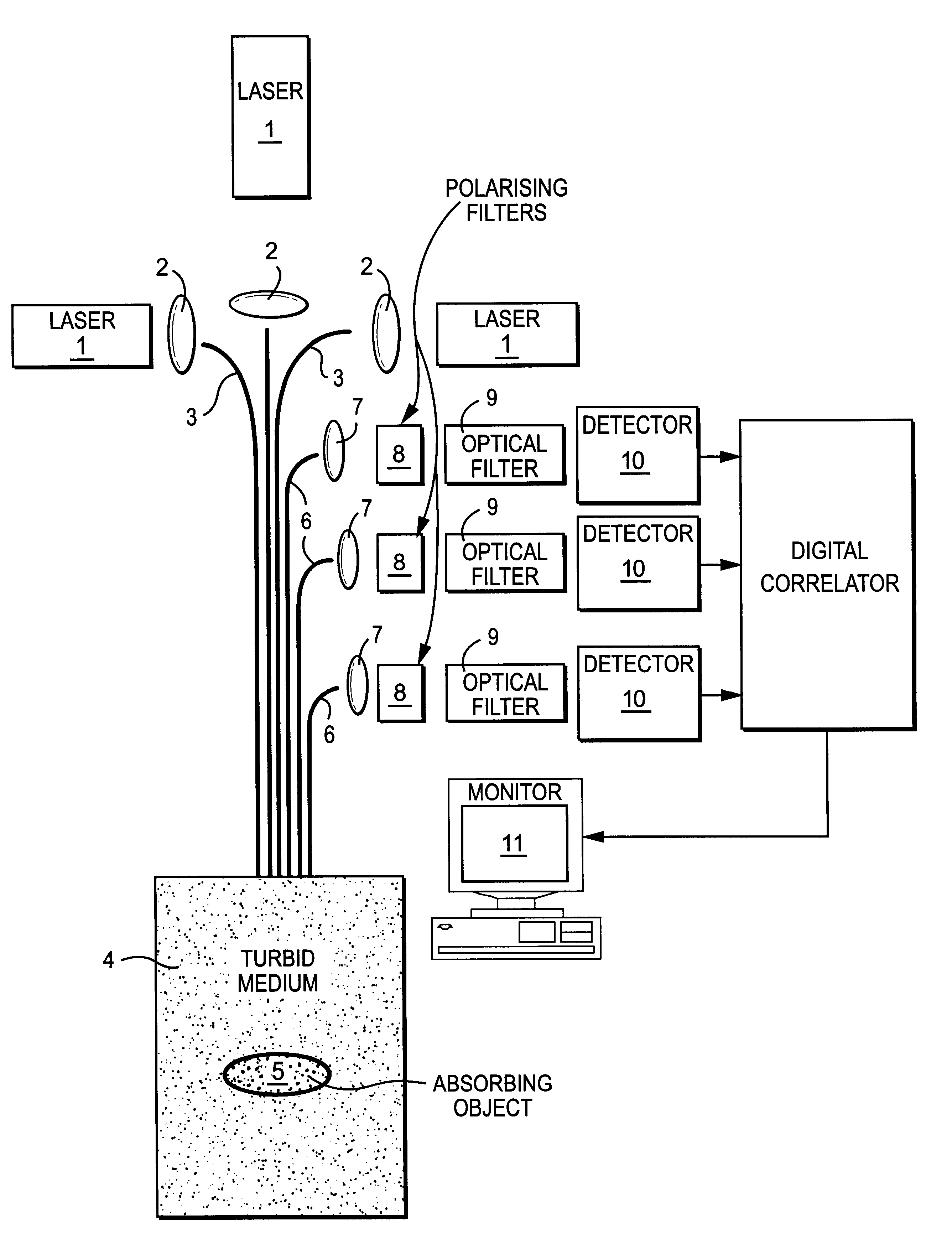
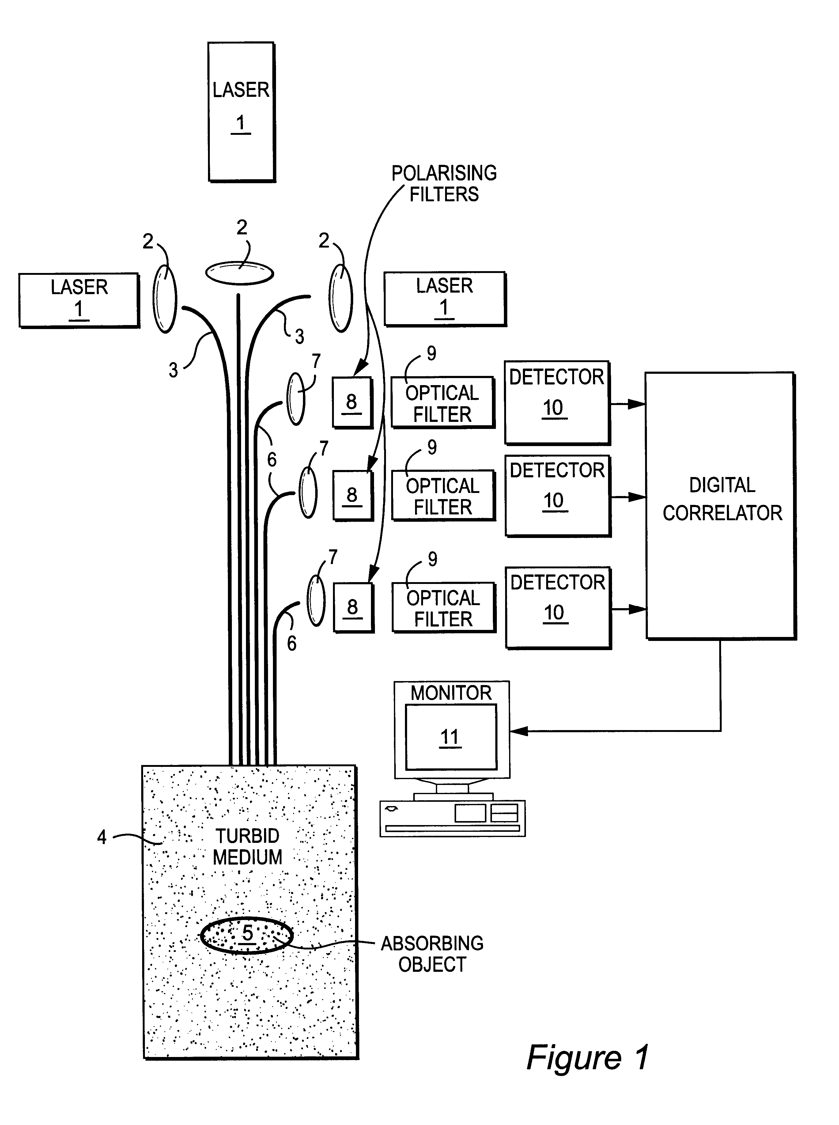
FIG. 1 shows an imaging apparatus comprising three lasers 1 operating at different wavelengths. The three lasers produce light wavelengths 488 nm (argon ion), 633 nm (helium neon) and 1064 nm (Nd:YAG) respectively, the light from each laser 1 having a single transverse and longitudinal mode. Optics 2 (an example of which is described in more detail below with reference to FIG. 6) couple light from each laser 1 into a single mode polarisation maintaining optical fibre 3. Light from each fibre 3 is launched into a turbid medium 4 within which is located an absorbing object 5.

Light scattered by the turbid medium 4 is collected by three optical fibres 6 which may have the same construction as the launch fibres 3. The collected light is collimated using farther optics 7 (an example of which is described in more detail below with reference to FIG. 7) and directed at polarising filters 8 and laser-line optical filters 9. Light transmitted by the laser-line filters 9 is monitored by detecto...


PUM


Abstract

A method of detecting an object located within a dynamic scattering media, includes i) directing a continuous coherent light wave of predetermined wavelength into the media; ii) detecting dynamically scattered light emerging from the media; iii) correlating the detected light photons in the time or frequency domain; iv) determining the presence of an object from analysis of differences between the correlation and a correlation which would arise from photons scattered by the media only; and v) determining the approximate position of the object within the media from the analysis of the correlation and knowledge of the mean transport path of the light wave of predetermined wavelength within the media.

Description

1. Field of the InventionThe present invention relates to a method and apparatus for detecting and / or imaging an object.2. Related ArtImage through turbid media is often carried out using Time of Flight measurements. Various methods of time of flight measurement are known. The majority of these methods measure the time taken by pulses of light to travel a return path. Since the velocity of light is both constant and known for most materials, measurements of time of flight can be readily converted into images of the medium through which the light has passed.Time of Flight imaging is particularly useful when imaging over large distances or in semi-turbid media. However, when dealing with short distances image resolution decreases rapidly, since the speed of light is so great that, for example, a spatial resolution of 1 m will require a detector with a temporal resolution of 5 ns. The shortest measurable distance and the image resolution obtainable using Time of Flight imaging is thus ...

Claims


Application Information

Patent Timeline
IPC IPC(8): A61B5/00G01N21/47A61B10/00G01B11/00G01N21/17G01N21/49
CPCA61B5/0073G01N21/4795
Inventor LLOYD, CHRISTOPHER J.CLARKE, DAVID J.
Owner VICTORIA VNIVERSITY OF MANCHESTER THE
Why Eureka
Try Eureka