
Microporous glass waveguides doped with selected materials

a micro-porous glass and waveguide technology, applied in glass making apparatus, instruments, cladding optical fibres, etc., can solve the problems of coupling losses between the two waveguides, polarization dependence on the transmission properties, and devices using electro-optic materials are limited to planar

Inactive Publication Date: 2004-06-15
INSTITUT NATIONAL D'OPTIQUE
View PDF9 Cites 4 Cited by
  • Summary
  • Abstract
  • Description
  • Claims
  • Application Information

AI Technical Summary

Benefits of technology

The present invention relates to a new type of optical waveguide that can be used in optical fibers for telecommunications applications. The waveguide is made of porous glass, which has the advantage of being able to be easily aligned with optical fibers and the coupling between them is low. The porous glass has a circular symmetry, which matches the index of refraction of optical fibers, reducing coupling losses. The invention also includes the use of electro-optic materials in the waveguide, which can control the phase of light transmitted through the waveguide. The invention also provides a method for making the electro-optic fibers. Overall, the invention provides a new and improved way to control the properties of light in optical fibers.

Problems solved by technology

To the inventors' knowledge, devices using electro-optic materials are limited to planar waveguides, which poses two fundamental problems when trying to couple them to optical fibres.
First, the index profile of a planar waveguide does not possess the circular symmetry of an optical fibre index profile, which results in coupling losses between the two waveguides, as well as a polarization dependence on the transmission properties.
Secondly, the planar and voluminous structure of a planar waveguide does not permit an easy alignment of the core of the planar waveguide with the core of the optical fibre, increasing the costs.
One could also add that in some cases, the index of refraction of the planar waveguide is considerably greater than that of the optical fibre, which causes problems due to Fresnel reflections.
Existing polarizers are limited to single mode waveguides and Bragg gratings present limited diffraction efficiencies.

Method used


Image

  • Microporous glass waveguides doped with selected materials
  • Microporous glass waveguides doped with selected materials
  • Microporous glass waveguides doped with selected materials

Examples


Embodiment Construction

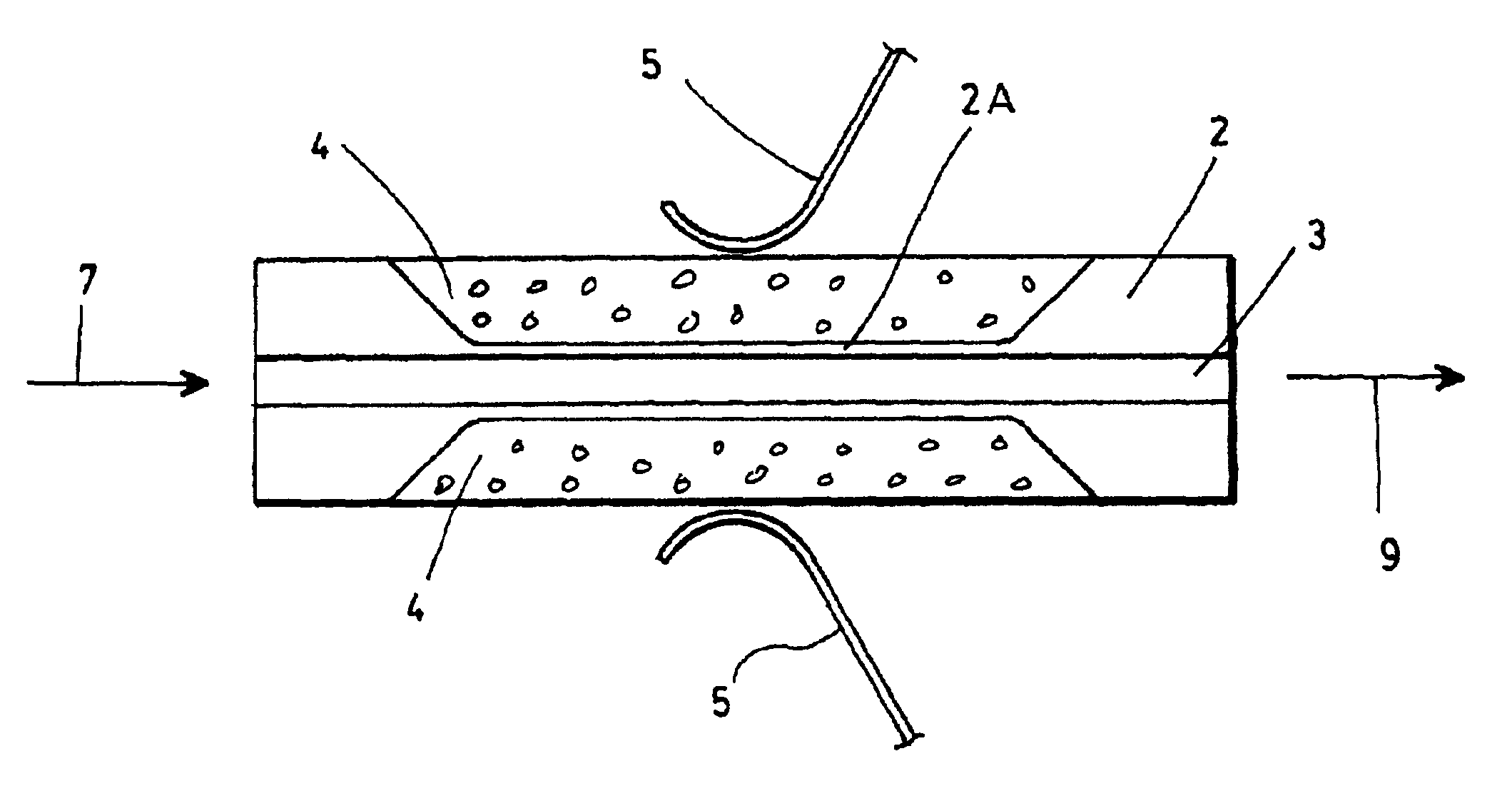
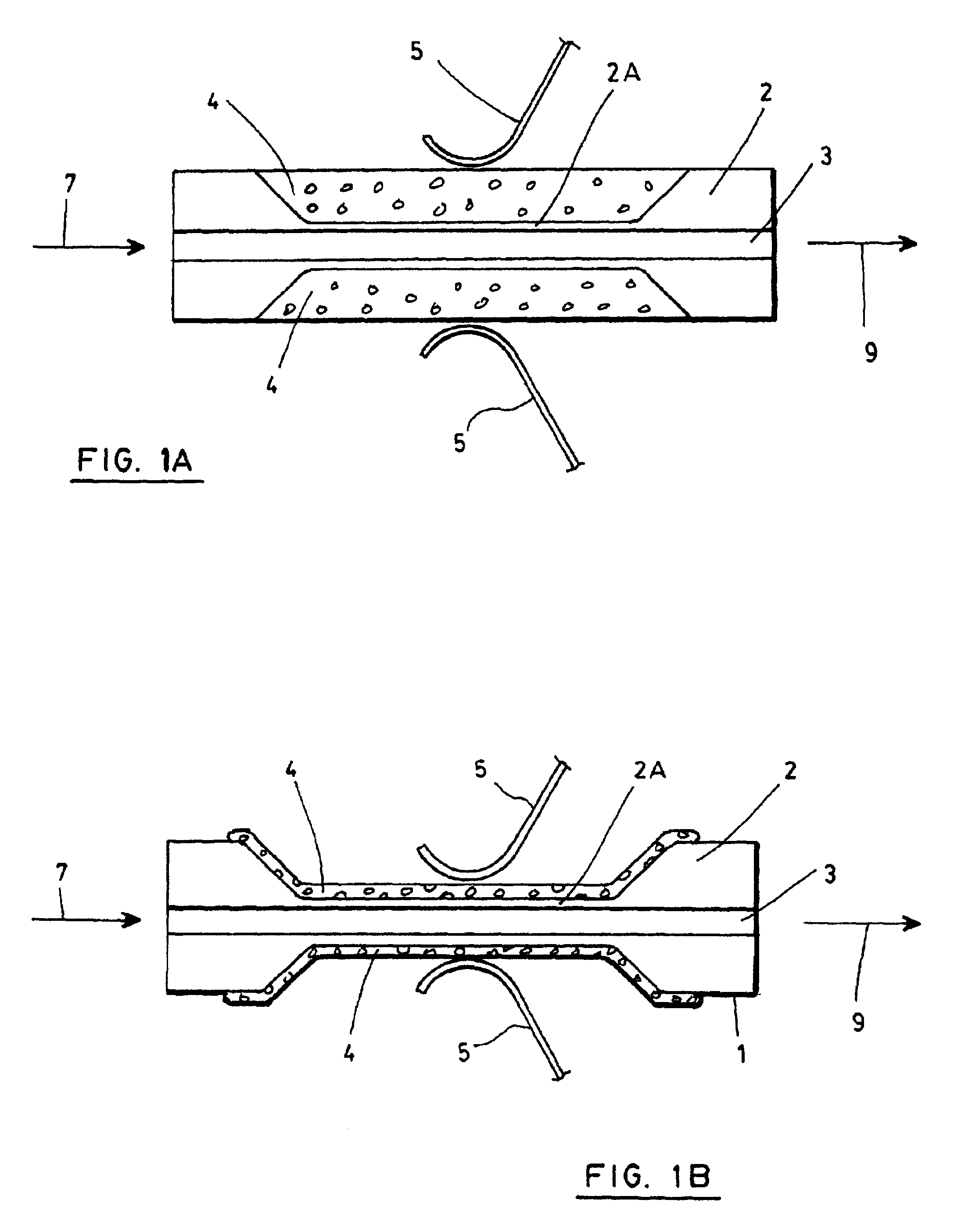
In order to properly situate the present invention, it is important to define what is meant in the present description by "porous glass", or "microporous glass" or "porous silica". These expressions, which can be used interchangeably, designate a glass, which is generally silica-based, containing a myriad of small, interconnected holes. These holes are called pores or micropores, and their size is almost always less than 10 nm. The holes are obtained in the glass by performing a chemical attack of a boron-silica glass, where the boron and alkaline constituents have been separated from the silica by a high temperature separation of phase and then placed in a solution by chemical attack, leaving a skeleton full of holes.

This type of porous glass must not be confused with porous soot, consisting of microparticles of silica and which is obtained by combustion of silicon tetrachloride. This agglomerate is often called, in the literature, porous glass, but it is not the same porous glass ...


PUM

PropertyMeasurementUnit
sizeaaaaaaaaaa
temperatureaaaaaaaaaa
optical activityaaaaaaaaaa

Abstract

The present invention concerns waveguides made from porous glass which have been doped with certain selected materials which exhibit optical properties. In the context of the invention, the selected materials are optical materials which exhibit optical activity or a Faraday effect, such as an electro-optic material, and more specifically a polymer. Devices made according to the present invention can be used as phase modulators.

Description

The present invention relates to microporous glass waveguides doped with selected materials, and more particularly to such glass waveguides for fibre optic applications.DESCRIPTION OF THE PRIOR ARTMany different devices have been proposed to control the property of light in optical materials, such as the polarization state, the phase or the intensity, particularly for application in optical fibre telecommunications. Among these different devices, a class of them use the property that electro-optic materials have to change the index of refraction upon application of an electric field. These latter devices are based on the principle of controlling the phase of the light travelling through the device, and have many applications. For example, in a Mach-Zender type interferometer configuration, the power transmitted can be controlled by modulating the phase of the light travelling in one of the arms of the interferometer.To the inventors' knowledge, devices using electro-optic materials ...

Claims


Application Information

Patent Timeline
Patent Type & Authority Patents(United States)
IPC IPC(8): C03C13/04C03C13/00C03C14/00G02B6/02G02F1/00G02B6/38
CPCC03C13/04C03C14/004G02B6/02076C03C2214/12G02B6/381G02F1/0036
Inventor CARON, SERGETAILLON, YVES
Owner INSTITUT NATIONAL D'OPTIQUE
Learn More