
Rotary component support system

Inactive Publication Date: 2004-06-15
VARIAN MEDICAL SYSTEMS
View PDF22 Cites 25 Cited by
  • Summary
  • Abstract
  • Description
  • Claims
  • Application Information

AI Technical Summary

Benefits of technology

Embodiments of the invention are particularly useful in anode grounded x-ray tubes, such as are commonly employed in computerized tomography ("CT") and other medical applications. In general however, embodiments of the invention are suitable for use in any application where it is desired to securely and reliably support a rotatable component in a desired position under a variety of operating conditions, and where it is desired to reduce or minimize the cost and expense associated with the disassembly of the rotary component support system.
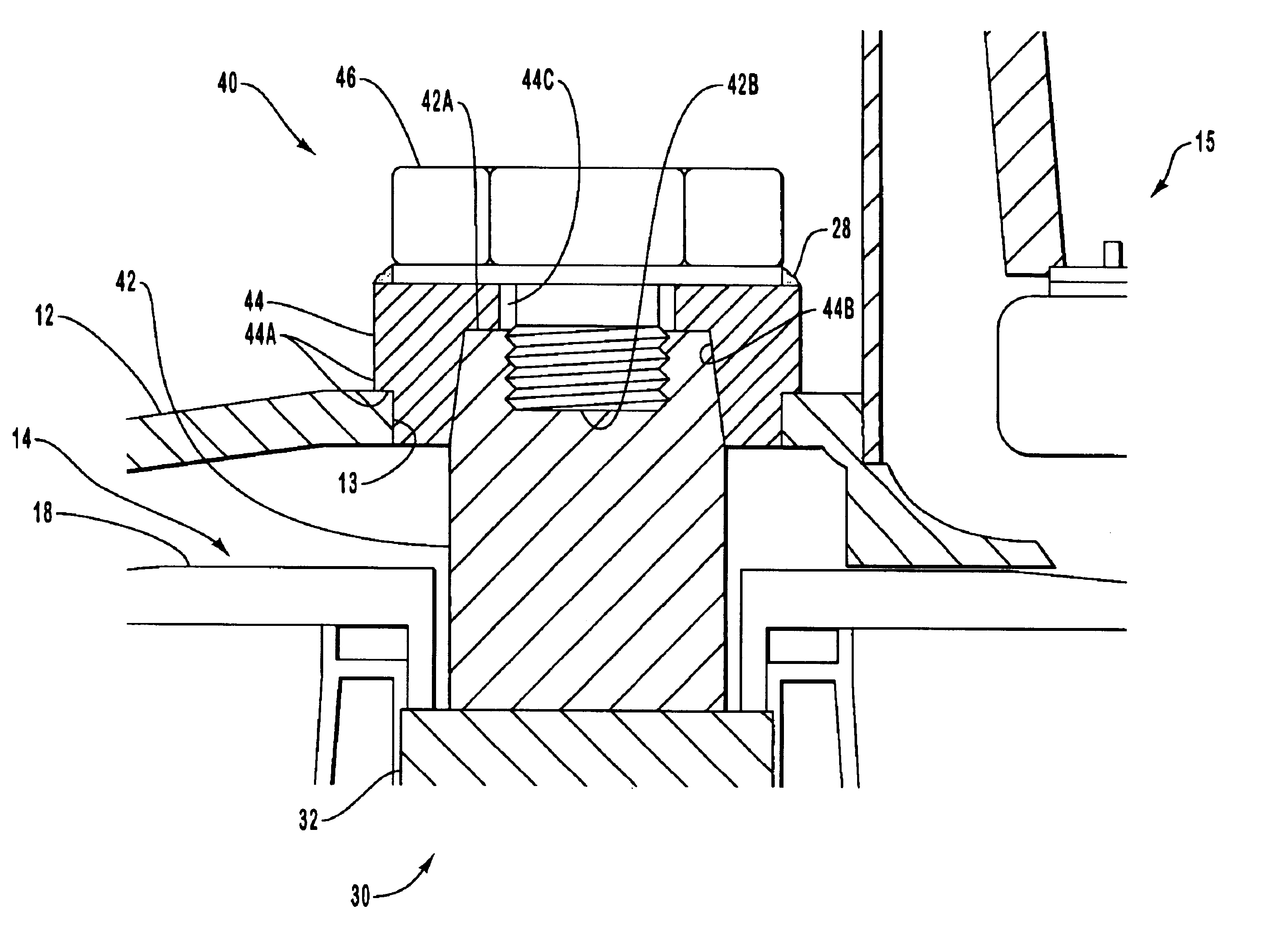
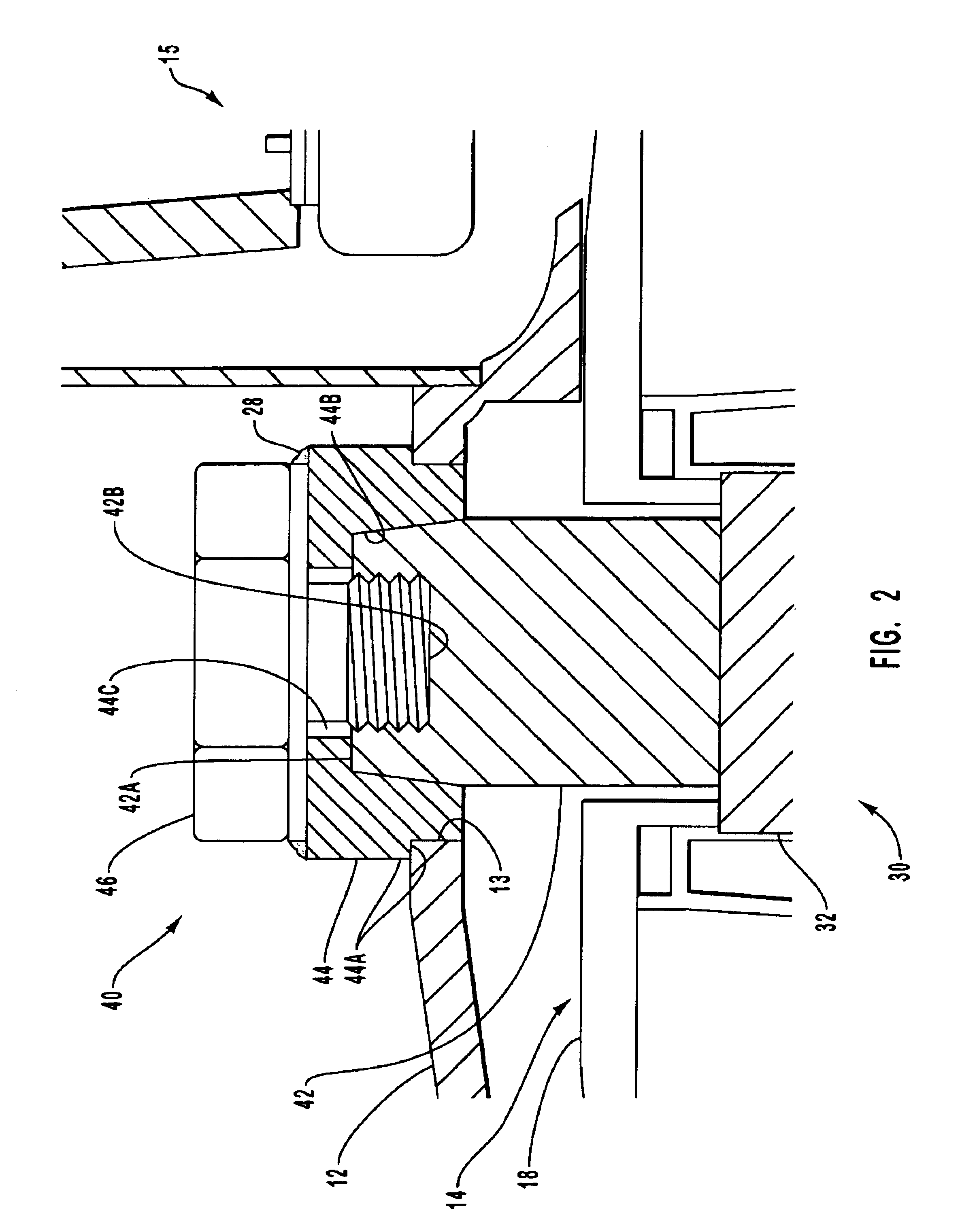
Because the mounting piece and support shaft have corresponding tapered geometries, the shaft can be readily and quickly aligned with the mounting piece without the need for time consuming adjustments. Alignment of the shaft contributes to the elimination of vibration and other undesirable phenomena often associated with unbalanced rotating components. Further, the bolt cooperates with the tapered geometries of the mounting piece and shaft to facilitate ready separation of the mounting piece and shaft should such a need arise. In particular, the weld on the interface between the bolt and mounting piece can be easily ground off, or otherwise removed, so that disassembly is accomplished by removing the bolt and pulling the mounting piece and support shaft apart from each other.

Problems solved by technology

This heat can reach extremely high temperatures that can damage the anode structure over time, and can reduce the operating life of the x-ray tube and / or the performance and operating efficiency of the tube.
While such anodes generally facilitate a desirable increase in the overall performance of the x-ray tube, the increased size and / or speed of those anodes often can cause other undesirable problems with respect to other portions of the x-ray tube.
Any migration of the focal spot due to vibration or other instabilities can reduce the image quality of the x-ray tube.
As suggested above however, such results are not achieved in all cases due to relative increases in the size and weights of anodes now in use, the operational speeds at which such anodes are employed, and / or the extreme thermal stresses imposed on the anode and its mounting system.
In particular, the weights and operational speeds of many anodes can cause various components of the anode mounting system to loosen over time.
Such high rates of acceleration introduce various mechanical stresses and strains that often compromise the integrity of the anode mounting system components, and may cause such components to loosen over a period of time.
However, removal of the anode from the x-ray tube, has often proven difficult.
These difficulties are often associated with the configuration and layout of the anode mounting system.
This configuration can be especially difficult to disassemble.
While this is effective in tightly fitting the shaft and sleeve together, it also creates a bond between the sleeve and the support shaft that is very difficult to break.
Further, when the bond is broken, damage may occur to the shaft, sleeve, anode, and / or vacuum enclosure.
Consequently, disassembly can result in added expense when repairing or replacing tube components and may even render the entire x-ray tube inoperable.
While it may be possible in some instances to minimize the damage that may occur during separation of the shaft and sleeve, the processes necessary to achieve such results are typically expensive and time consuming.

Method used


Image

  • Rotary component support system
  • Rotary component support system
  • Rotary component support system

Examples


Embodiment Construction

Reference will now be made to figures wherein like structures will be provided with like reference designations. It is understood that the drawings are diagrammatic and schematic representations and are not necessarily drawn to scale. Moreover, the drawings merely illustrate examples of presently preferred embodiments, and are not limiting with respect to the scope of the present invention.

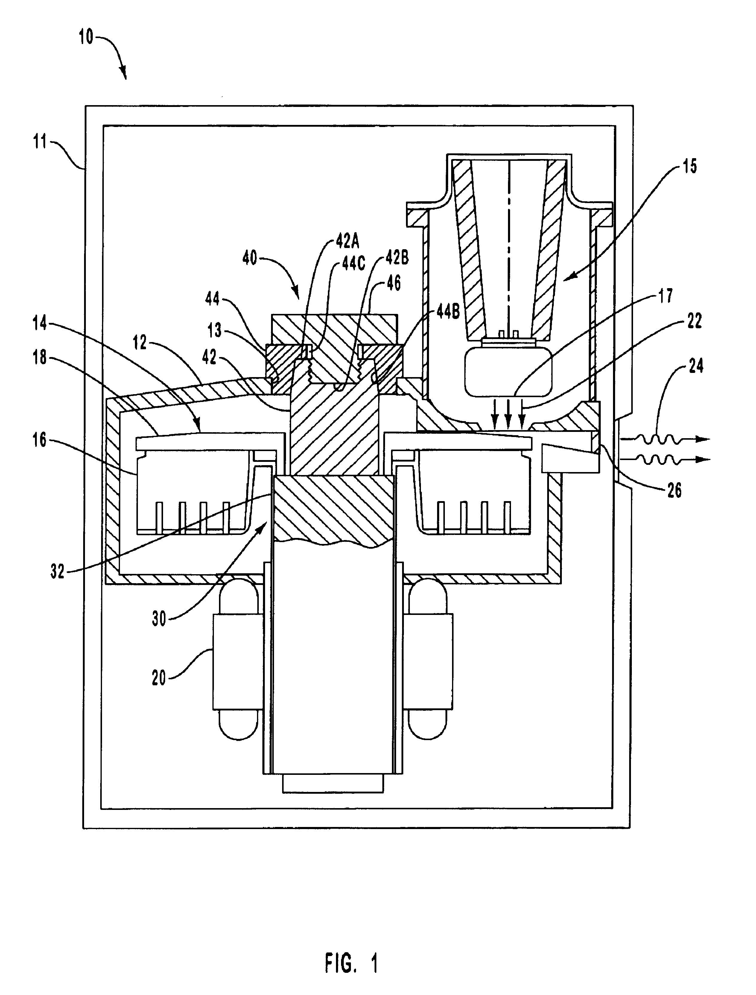
Reference is first made to FIG. 1, which illustrates selected features of an x-ray tube, designated generally at 10. In this embodiment, the x-ray tube 10 comprises an anode grounded type x-ray tube such as may be employed in CT applications. However, embodiments of the invention are suitable for use with other types of x-ray tubes, and in various other devices as well. Accordingly, the scope of the present invention should not be construed to be limited to this exemplary operating environment.

The x-ray tube 10 includes a housing 11 within which is disposed a housing defining a vacuum enclosure 12...


PUM


Abstract

A rotary component support system for positioning and securing an anode of x-ray tube. The rotary component support system includes a shaft, to which the anode is indirectly mounted, that includes a tapered end and defines a threaded hole. The tapered end of the shaft is engaged by a tapered cavity defined by a mounting piece that is disposed in an aperture defined by the vacuum enclosure of the x-ray tube. The mounting piece defines a hole through which a bolt passes. The bolt engages the threaded hole defined by the support shaft so that as the bolt is tightened, the tapered end of the support shaft is drawn into the tapered cavity of the mounting piece. Due to the tapered geometries, the support shaft self-aligns itself with respect to the mounting piece. A weld at the interface between the bolt and the mounting piece seals the vacuum enclosure.

Description

1. The Field of the InventionThe present invention generally relates to support systems for use in conjunction with components designed for rotary motion. More particularly, the present invention relates to a rotary component support system for a rotating anode of an x-ray tube.2. Related TechnologyX-ray generating devices are extremely valuable tools that are used in a wide variety of applications, both industrial and medical. For example, such equipment is commonly employed in areas such as medical diagnostic examination and therapeutic radiology, semiconductor fabrication, and materials analysis.Regardless of the applications in which they are employed, most x-ray generating devices operate in a similar fashion. X-rays are produced in such devices when electrons are accelerated to high speeds and then impinged upon a material of a particular composition. This process typically takes place within an evacuated housing of an x-ray tube located in the x-ray generating device. The x-r...

Claims


Application Information

Patent Timeline
IPC IPC(8): H01J35/10H01J35/00
CPCH01J35/101
Inventor BARRETT, VAUGHN LEROY
Owner VARIAN MEDICAL SYSTEMS
Learn More