
Lens assembly alignement device for camera lens module

Inactive Publication Date: 2010-08-19
SAMSUNG ELECTRONICS CO LTD
View PDF21 Cites 13 Cited by
  • Summary
  • Abstract
  • Description
  • Claims
  • Application Information

AI Technical Summary

Benefits of technology

[0010]The present invention has been made to address at least the above problems and / or disadvantages and to provide at least the advantages described below. Accordingly, an aspect of the present invention provides an alignment device which can readily align optical axes between optical elements for a camera lens module.
[0011]Another aspect of the present invention provides an alignment device which is capable of executing the alignment of optical axes between optical elements even in a camera lens module to be equipped in an information device, such as a portable terminal, thereby optimizing the performance of the individual optical elements provided in the camera lens module.
[0012]A further aspect of the present invention provides an alignment device which is capable of executing the alignment of optical axes between optical elements in a camera lens module, thereby contributing to the improvement of quality of photographed image of the camera lens module.

Problems solved by technology

However, if the optical axes of the image sensor and the lens are not properly aligned with each other, the performance of the camera lens module is deteriorated even when the performance and quality of its individual optical elements are excellent.
However, proper alignment between optical elements has not been yet been provided in camera lens modules equipped in an information device, such as a portable terminal.
Thus, even if a camera lens module is configured with high performance and high quality optical elements, there is a limit in improving the quality of photographed images of the camera lens module.

Method used


Image

  • Lens assembly alignement device for camera lens module
  • Lens assembly alignement device for camera lens module
  • Lens assembly alignement device for camera lens module

Examples


Embodiment Construction

[0022]Embodiments of the present invention are described in detail with reference to the accompanying drawings. In the following description, the same or similar elements may be designated by the same or similar reference numerals although they are shown in different drawings. Further, various specific definitions found in the following description, such as specific values of packet identifications, contents of displayed information, etc., are provided only to help general understanding of the present invention, and it is apparent to those skilled in the art that the present invention can be implemented without such definitions. Detailed descriptions of constructions or processes known in the art may be omitted to avoid obscuring the subject matter of the present invention.

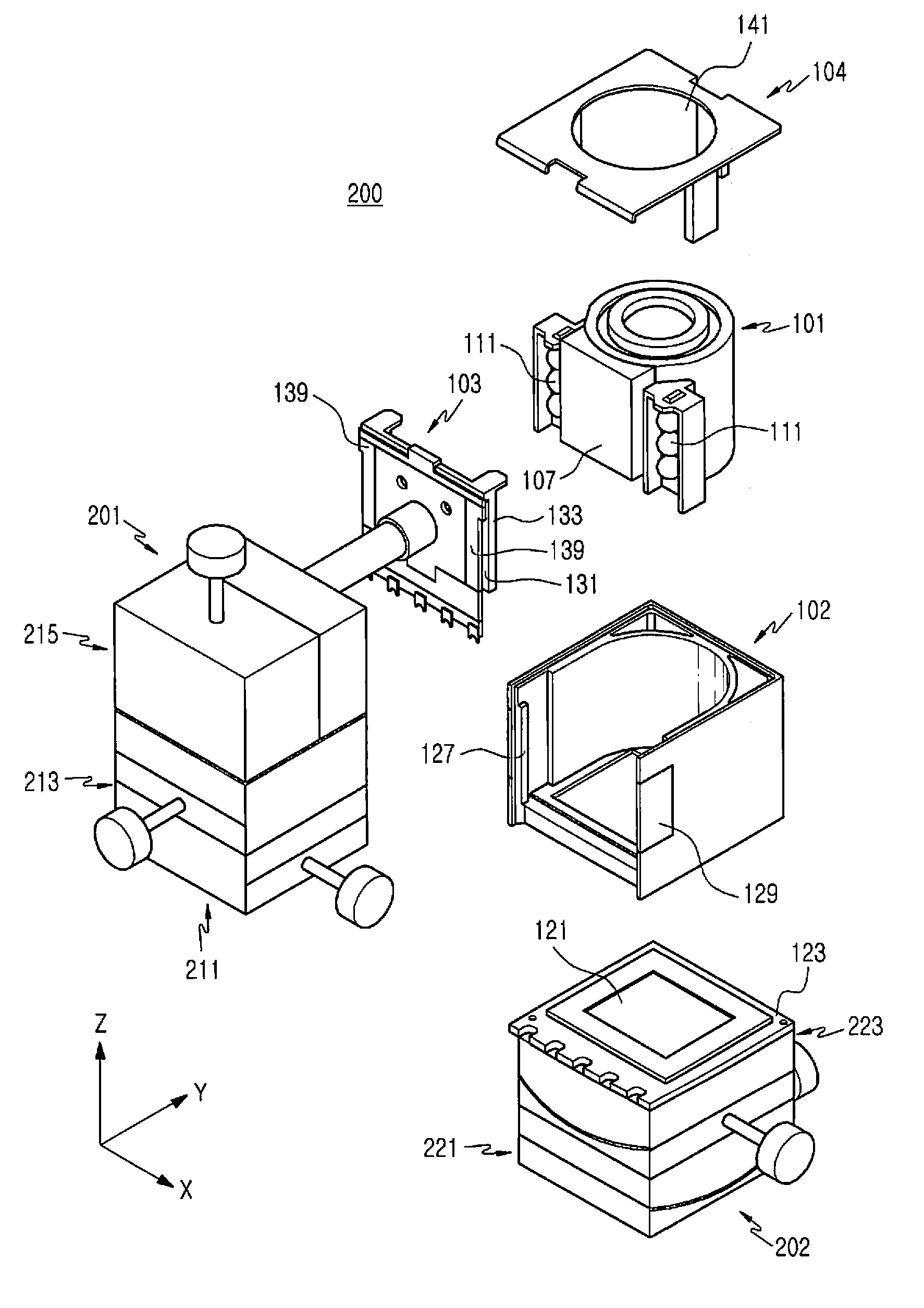
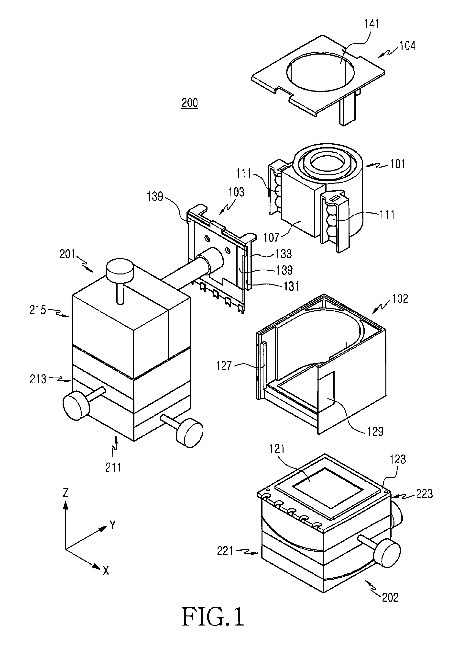
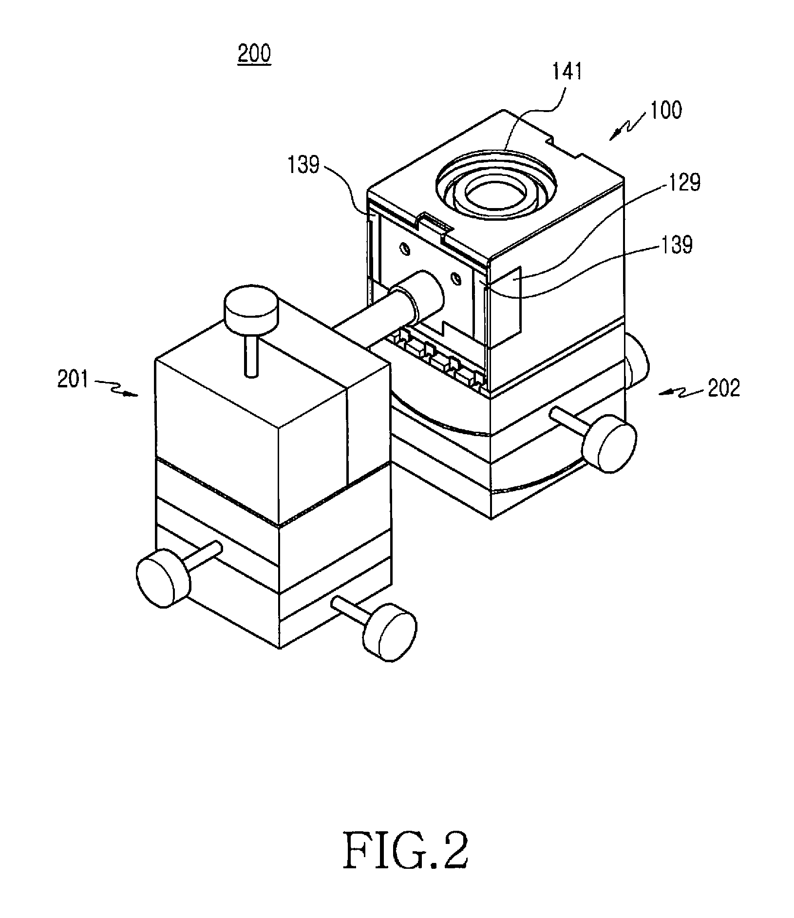
[0023]As shown in FIGS. 1 to 5, a lens assembly alignment device 200 for a camera lens module, according to an embodiment of the present invention, includes a position alignment apparatus 201 and a slant alignment...


PUM

PropertyMeasurementUnit
Optical propertiesaaaaaaaaaa

Abstract

A lens assembly alignment apparatus for a camera lens module is provided. The lens assembly alignment apparatus includes a position alignment apparatus that moves a lens assembly in a direction of an optical axis of the lens assembly and on a plane perpendicular to the optical axis. The apparatus also includes a slant alignment apparatus having first and second rotary axes which extend perpendicular to each other and perpendicular to the optical axis of the lens assembly, respectively. The lens assembly is received in a housing, and the slant alignment apparatus aligns an optical axis of an image sensor, which is mounted in the housing, parallel to the optical axis of the lens assembly by rotating the housing about each of the first and second rotary axes.

Description

PRIORITY[0001]This application claims priority under 35 U.S.C. §119(a) to an application entitled “Lens Assembly Alignment Device For Camera Lens Module” filed in the Korean Intellectual Property Office on Feb. 16, 2009 and assigned Serial No. 10-2009-0012402, the content of which is incorporated herein by reference.BACKGROUND OF THE INVENTION[0002]1. Field of the Invention[0003]The present invention relates generally to a camera lens module, and more particularly, to a lens assembly alignment device for aligning the optical axis of the lens assembly with the optical axis of an image sensor when mounting the lens assembly in a camera lens module.[0004]2. Description of the Related Art[0005]A digital camera converts an image signal into an electric signal, and thereby electrically executes all signal processing, such as recording, reproducing, etc. The digital camera does not require a darkroom processes or chemical treatments like a silver salt film camera. The digital camera also a...

Claims


Application Information

Patent Timeline
IPC IPC(8): B25B27/14
CPCG03B5/00H04N5/2252H04N5/2253H04N5/2254Y10T29/53913Y10T29/53987Y10T29/53261Y10T29/53978H04N5/2257H04N23/51H04N23/54H04N23/57H04N23/55H04N23/00
Inventor KO, KIL-SOOSHIN, DOO-SIK
Owner SAMSUNG ELECTRONICS CO LTD
Learn More